


1.启动Workbench 18.0
在“开始”菜单中执行ANSYS 18.0→Workbench 18.0命令。
2.创建结构静力分析
(1)在工具箱【Toolbox】的【Analysis Systems】中双击或拖动结构静力分析【Static Structural】到项目分析流程图,如图2-22所示。
(2)在Workbench的工具栏中单击【Save】,保存项目实例名为Clamp.wbpj。工程实例文件保存在D:\AWB\Chapter02文件夹中。
3.创建材料参数
(1)编辑工程数据单元:右键单击【Engi-neering Data】→【Edit】。
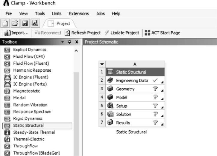
图2-22 创建结构静力分析
(2)在工程数据属性中增加材料:在Work-bench的工具栏中单击 工程材料源库,此时的主界面显示【Engineering Data Sources】和【Outline of Favorites】。选择A3栏【General materials】,从【Outline of General materials】里查找铜合金【Copper Alloy】材料,然后单击【Outline of General Material】表中的添加按钮
 ,此时在C6栏中显示标示
 ,表明材料添加成功,如图2-23所示。
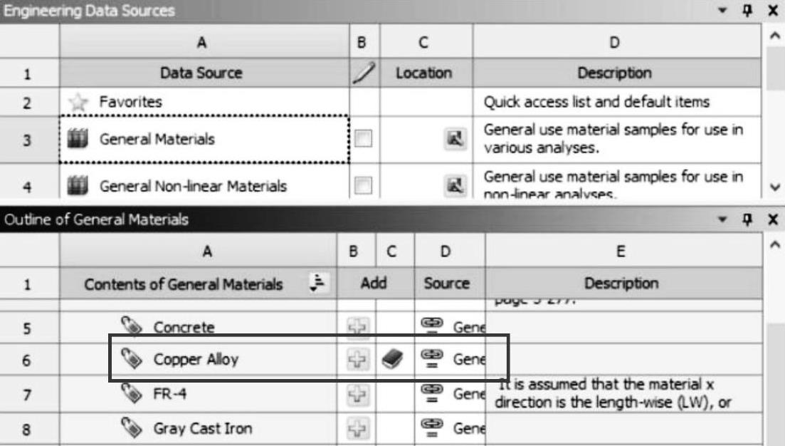
图2-23 创建材料
(3)单击工具栏中的【A2:Engineering Data】关闭按钮,返回到Workbench主界面,新材料创建完毕。
4.导入几何模型
在结构静力分析上,右键单击【Geometry】→【Import Geometry】→【Browse】→找到模型文件Clamp.x_t,打开导入几何模型。模型文件在D:\AWB\Chapter02文件夹中。
5.进入Mechanical分析环境
(1)在结构静力分析上,右键单击【Model】→【Edit】进入Mechanical分析环境。
(2)在Mechanical的主菜单【Units】中设置单位为Metric(mm,kg,N,s,mV,mA)。
6.为几何模型分配材料
(1)为圆管分配材料:在导航树上单击【Geometry】展开→【Pipe】→【Details of“Pipe”】→【Material】→【Assignment】=Copper Alloy。
(2)卡箍、螺栓和螺母的材料默认为结构钢。
7.定义局部坐标
在Mechanical标准工具栏中单击 ,选择螺栓外表面;在导航树上右键单击【Coordinate Systems】,从弹出的快捷菜单中选择【Insert】→【Coordinate Systems】,【Coordinate System】→【Details of“Coordinate System”】→【Principal Axis】→【Axis】=Z,其他默认,如图2-24所示。
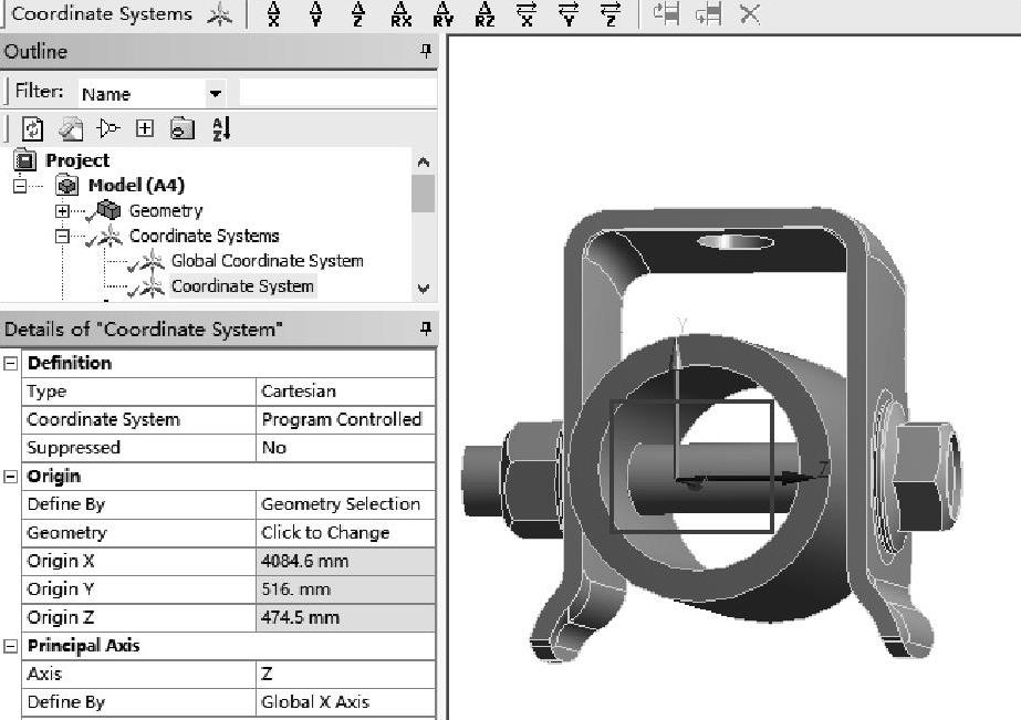
图2-24 局部坐标设置
8.接触设置
(1)在导航树上右键单击【Connections】→【Rename Based On Definition】,重新命名目标面与接触面。
(2)设置圆管与卡箍的接触:在导航树上展开【Connections】→【Contacts】,单击【Bond-ed-Holder To Pipe】→【Details of“Bonded-Holder To Pipe”】→【Definition】→【Type】=Frictional,【Frictional Coefficient】=0.15,【Behavior】=Symmetric;【Advanced】→【Formulation】=Aug-mented Lagrange,【Detection Method】=On Gauss Point;【Geometric Modification】→【Interface Treatment】=Adjust to Touch,其他默认,如图2-25所示。
(3)设置螺栓头与卡箍表面的接触:单击【Bonded-Holder To Bolt】→【Details of“Bond-ed-Holder To Bolt”】→【Scope】→【Contact】:单击3Faces,在空白处单击,单击 选择卡箍侧面圆区域,然后单击【Apply】确定,如图2-26所示;【Target】:隐藏整个卡箍,单击4Faces,在空白处单击,单击
 选择卡箍侧面圆区域对应的螺栓头面,然后单击【Apply】确定,如图2-27所示;单击【Definition】→【Type】=Frictional,【Frictional Coefficient】=0.15,【Behavior】=Symmetric;【Advanced】→【Formulation】=Augmented Lagrange,【Detection Meth-od】=On Gauss Point,【Geometric Modification】→【Interface Treatment】=Add Offset,Ramped Effects,其他默认,如图2-28所示。
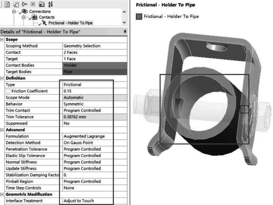
图2-25 摩擦接触设置
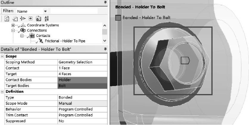
图2-26 设置摩擦接触面
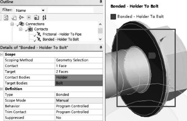
图2-27 设置摩擦接触目标面
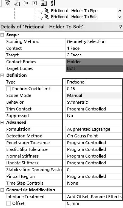
图2-28 摩擦接触设置
(4)设置螺母与卡箍表面的接触:单击【Bonded-Holder To Nut】→【Details of“Bonded-Holder ToNut”】→【Definition】→【Type】=Frictional,【Frictional Coefficient】=0.15,【Behav-ior】=Symmetric;【Advanced】→【Formulation】=Augmented Lagrange,【Detection Method】=On Gauss Point,【Geometric Modification】→【Interface Treatment】=Add Offset,Ramped Effects,其他默认,如图2-29所示。
(5)设置螺栓杆与圆管的接触:单击【Bonded-PipeTo Bolt】→【Details of“Bonded-Pipe To Bolt”】→【Definition】→【Type】=Frictionless,【Behavior】=Symmetric;【Advanced】→【Formulation】=Augmented Lagrange,【Detection Method】=On Gauss Point;【Geometric Modification】→【Interface Treatment】=Adjustto Touch,其他默认,如图2-30所示。
(6)设置螺栓杆与螺母的接触:单击【Bonded-Nut To Bolt】→【Details of“Bonded-Nut To Bolt”】→【Definition】→【Be-havior】=Symmetric;【Advanced】→【Formulation】=Pure Penalty,【Detection Method】=On Gauss Point,其他默认,如图2-31所示。
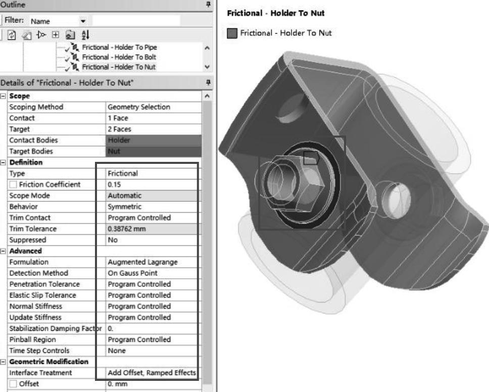
图2-29 摩擦接触设置
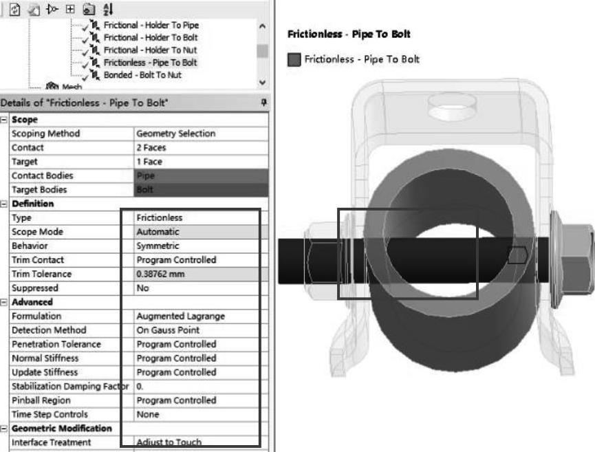
图2-30 无摩擦接触设置
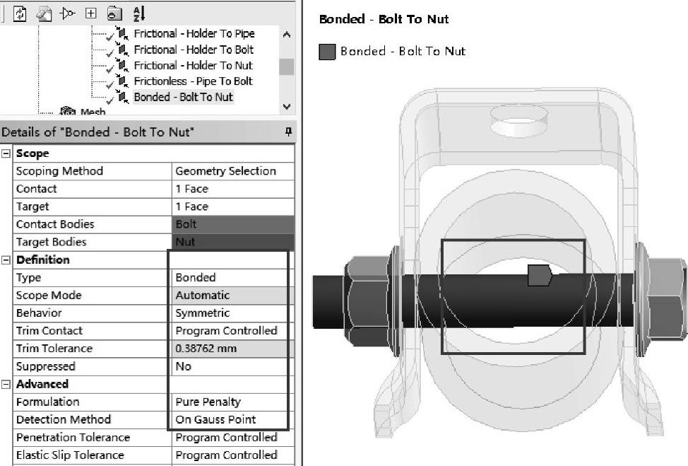
图2-31 螺母接触设置
(7)设置螺栓杆与卡箍的接触:在导航树上单击【Contacts】,从连接工具栏中单击【Contact】→【Friction-less】,单击【Frictionless-No Selection To No Selection】→【Details of“Fric-tionless-No Selection To No Selec-tion”】→【Contact】:隐藏螺栓和圆管,单击 选择卡箍两侧孔内表面,单击【Contact】右方的【No Se-lection】,然后单击【Apply】确定,如图2-32所示。【Target】:显示隐藏的螺栓和圆管,单击
 选择螺栓杆表面,单击【Target】右方的【No Selection】,然后单击【Apply】确定,如图2-33所示。单击【Frictionless-Holder To Bolt】→【Details of“Frictionless-Holder To Bolt”】→【Definition】→【Behavior】=Symmetric;【Ad-vanced】→【Formulation】=Augmented Lagrange,【Detection Method】=On Gauss Point;【Geomet-ric Modification】→【Interface Treatment】=Add Offset,No Ramping,其他默认,如图2-34所示。
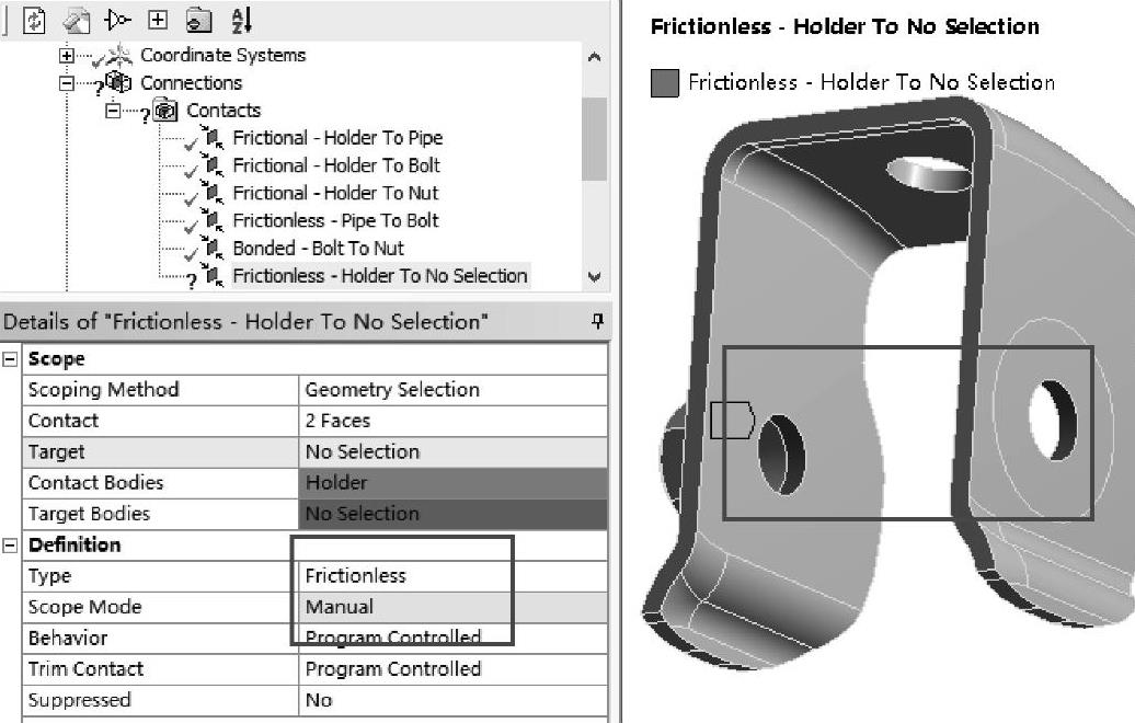
图2-32 设置无摩擦接触面
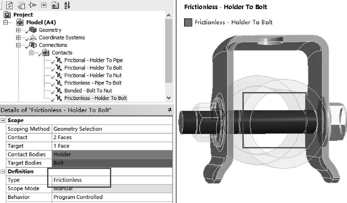
图2-33 设置无摩擦接触目标面(https://www.xing528.com)
9.划分网格
(1)在导航树里单击【Mesh】→【Details of“Mesh”】→【Defaults】→【Physics Preference】=Mechanical,【Relevance】=80;【Sizing】→【Size Function】=Curvature,【Relevance Center】=Medium,【Span Angle Center】=Medium,其他默认。
(2)在标准工具栏中单击 ,选择所有几何模型,然后在导航树上右键单击【Mesh】,从弹出的菜单中选择【Insert】→【Sizing】→【Details of“Body Sizing”-Sizing】→【Definition】→【Element Size】=2mm,其他默认。
(3)生成网格:右键单击【Mesh】→【Generate Mesh】,图形区域显示程序生成的网格模型,如图2-35所示。
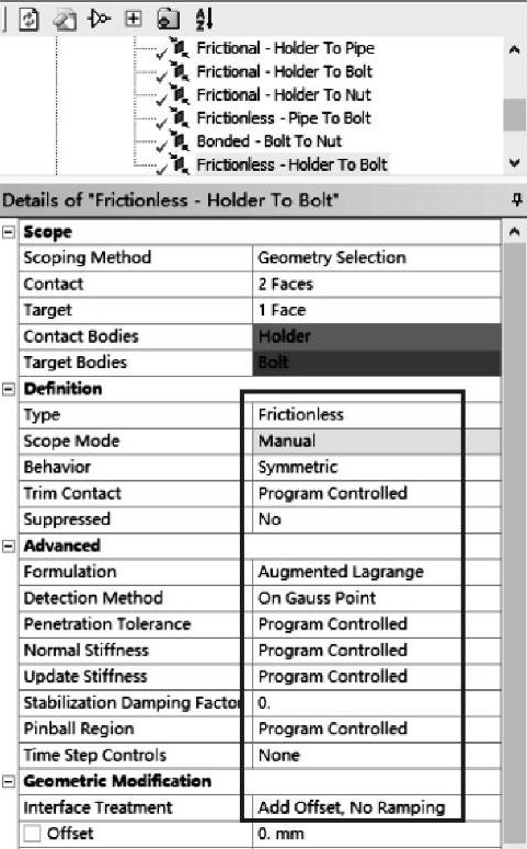
图2-34 无摩擦接触设置
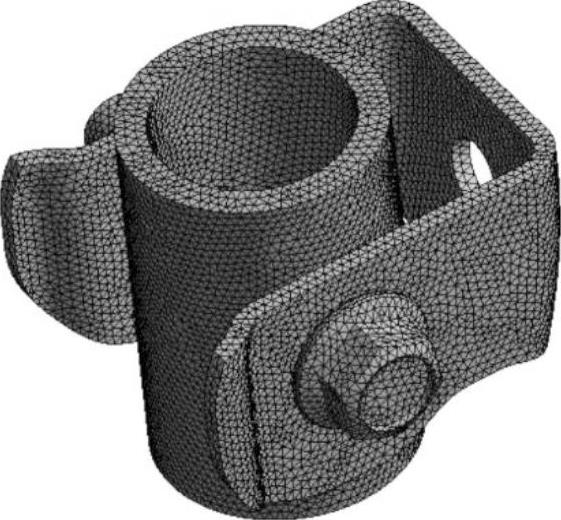
图2-35 划分网格
(4)网格质量检查:在导航树里单击【Mesh】→【Details of“Mesh”】→【Quality】→【Mesh Metric】=Element Quality,显示Element Quality规则下网格质量详细信息,平均值处在好水平范围内,展开【Statistics】显示网格和节点数量。
10.接触初始状态检测
(1)在导航树上,右键单击【Connections】→【Insert】→【Contact Tool】。
(2)右键单击【Contact Tool】,从弹出的快捷菜单中选择【Generate Initial Contact Re-sults】,经过初始运算,得到初始接触信息,如图2-36所示。注意图示接触状态值是按照网格设置后的状态,也可先不设置网格,查看接触初始状态。
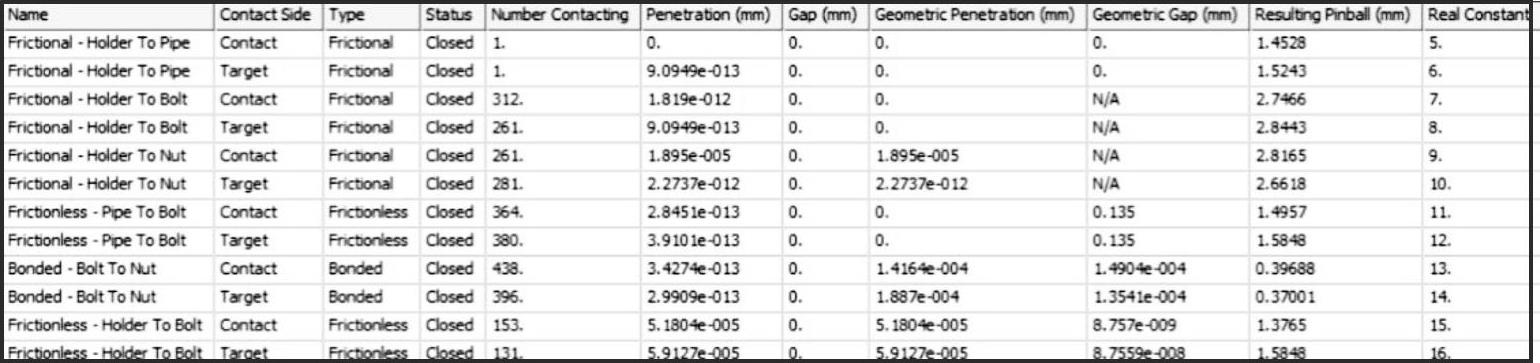
图2-36 接触初始状态检测
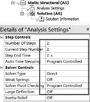
图2-37 非线性设置
11.施加边界条件
(1)单击【Static Structural(A5)】。
(2)非线性设置:单击【Analysis Settings】→【Details of“Analy-sis Settings”】→【Step Controls】→【Number Of Steps】=2,【Current Step Number】=2,【Step End Time】=2;【Solver Controls】→【Solver Type】=Direct,【Weak Spring】=Off,其他默认,如图2-37所示。
(3)施加预紧力:施加第1载荷步:首先在标准工具栏中单击 ,然后选择螺栓杆面,接着在环境工具栏中单击【Loads】→【Plot Pretension】→【Details of“Plot Pretension”】→【Definition】→【DefineBy】=Load,【Preload】输入1000N,如图2-38所示。施加第2载荷步:首先单击【Plot Pre-tension】,其次在【Graph】里单击黑色分界线往右边拖到2处,最后单击【Plot Pretension】→【Details of“Plot Pretension”】→【Definition】→【Define By】=Lock,如图2-39所示。
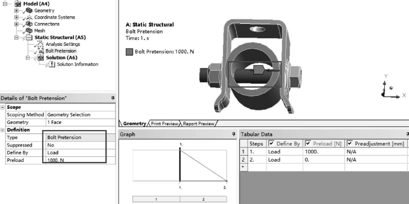
图2-38 施加第1载荷步
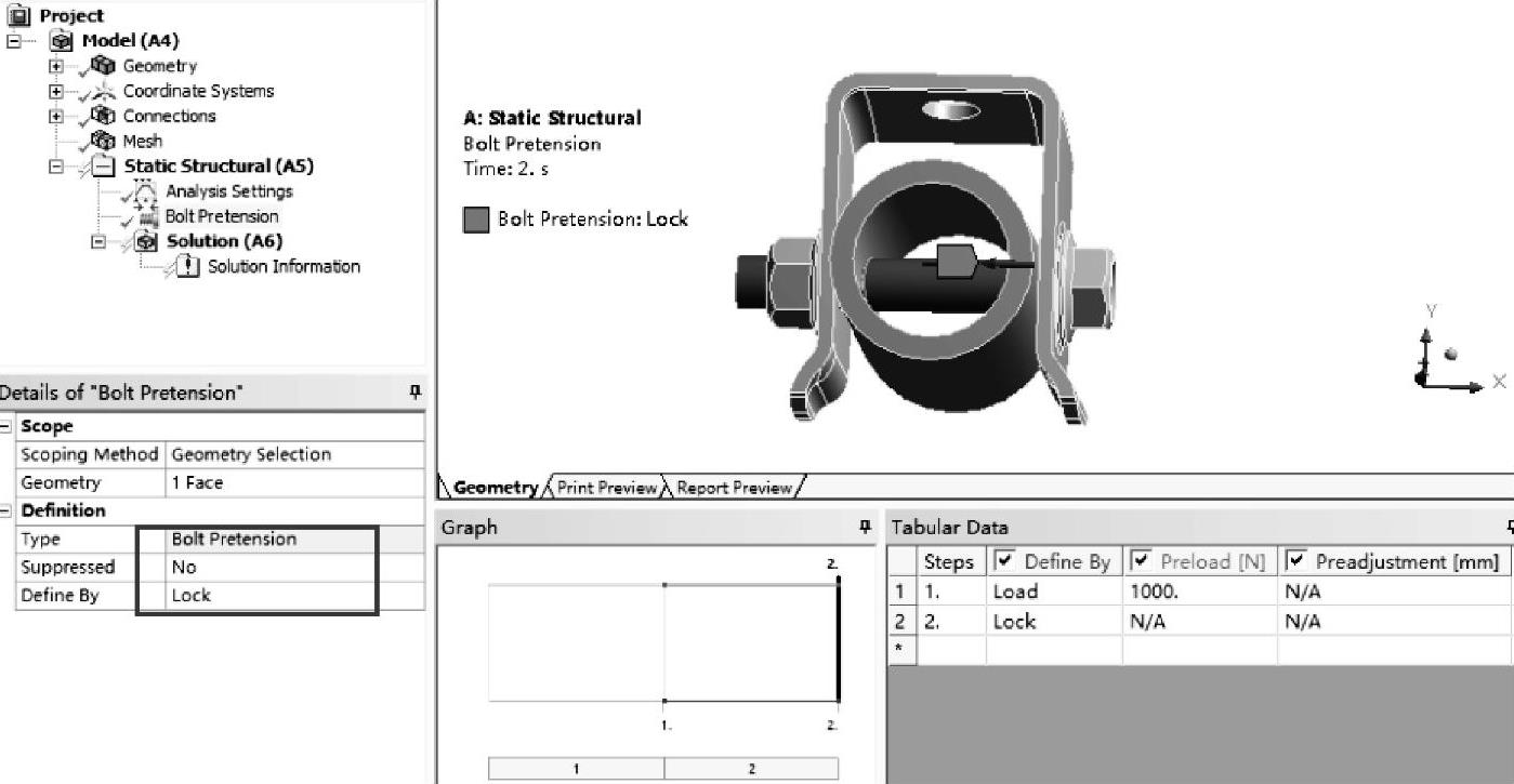
图2-39 施加第2载荷步
(4)施加约束:首先在标准工具栏中单击 ,然后选择卡箍上后面圆孔,接着在环境工具栏中单击【Supports】→【Fixed Support】,如图2-40所示。
12.设置需要的结果
(1)在导航树上单击【Solution(A6)】。
(2)在标准工具栏中单击 选择圆管,在求解工具栏中单击【Deformation】→【Direction-al】,【Directional Deformation】→【Details of“Directional Deformation”】→【Definition】→【Orien-tation】=Z Axis,【Coordinate System】=Coordinate System,如图2-41所示。
(3)在求解工具栏中单击【Deformation】→【Total】。
(4)在求解工具栏中单击【Stress】→【Equivalent(von-Mises)】。
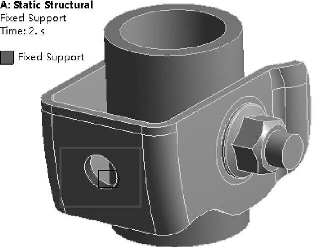
图2-40 施加约束
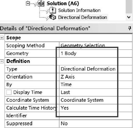
图2-41 方向变形设置
13.求解与结果显示
(1)在Mechanical标准工具栏中单击 进行求解运算。
(2)运算结束后,单击【Solution(A6)】→【Directional Deformation】,显示圆管Z方向的变形分布云图,如图2-42所示;单击【Solution(A6)】→【Total Deformation】,图形区域显示分析得到的圆管变形分布云图,如图2-43所示;单击【Solution(A6)】→【Equivalent Stress】,显示圆管等效应力分布云图,如图2-44所示。
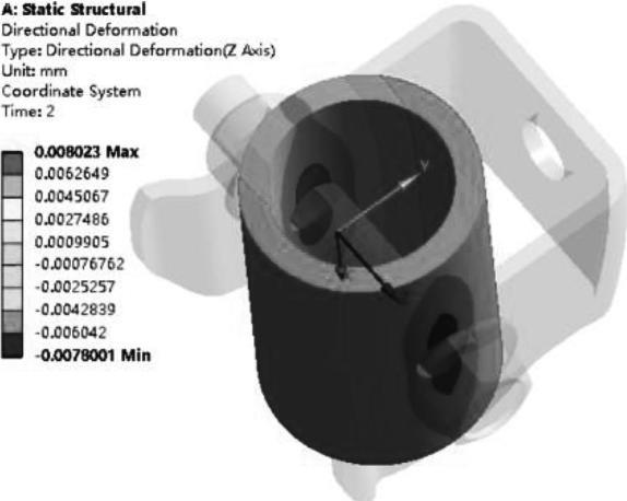
图2-42 Z方向变形分布云图
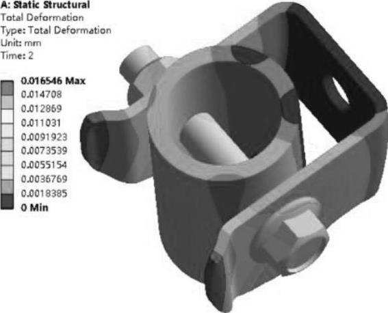
图2-43 圆管变形分布云图
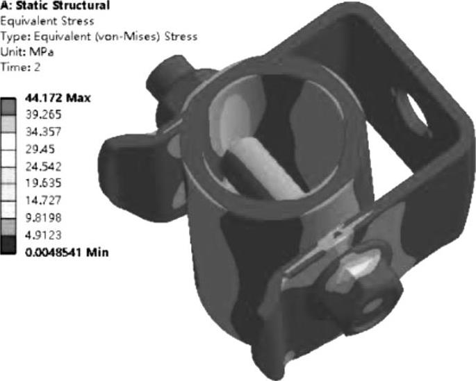
图2-44 圆管等效应力分布云图
(3)查看力收敛:在导航树上单击【Solution Information】→【Details of“Solution Informa-tion”】→【Solution Output】=Force Convergence,可以查看收敛曲线图,如图2-45所示。
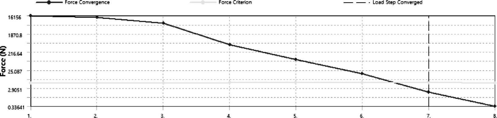
图2-45 力收敛图
14.保存与退出
(1)退出Mechanical分析环境:单击Mechanical主界面的菜单【File】→【Close Mechani-cal】退出环境,返回到Workbench主界面,此时主界面的分析流程图中显示的分析已完成。
(2)单击Workbench主界面上的【Save】按钮,保存所有分析结果文件。
(3)退出Workbench环境:单击Workbench主界面的菜单【File】→【Exit】退出主界面,完成分析。
免责声明:以上内容源自网络,版权归原作者所有,如有侵犯您的原创版权请告知,我们将尽快删除相关内容。