1)选择Mechanical APDL Product Launcher 15.0,弹出Mechanical APDL Product Launcher15.0窗口。设置参数、工作目录、工作名称,单击Run按钮进入ANSYS 15.0 GUI界面。
2)在GUI界面中选择Main Menu>Preferences命令,弹出图8-1所示的Preferences for GUI Filtering对话框,勾选Structural,单击OK按钮。
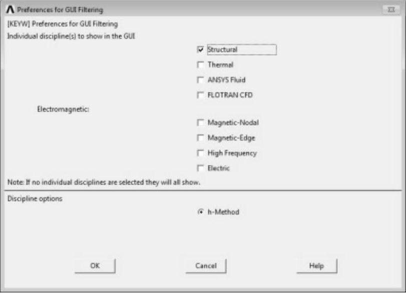
图8-1 Preferences for GUI Filtering对话框
3)在GUI界面中选择Utility Menu>WorkPlane>Change Active CS to>Global Cylindrica命令,将全局坐标修改为柱坐标。
4)在GUI界面中选择Main Menu>Preprocessor>Modeling>Create>Keypoints>In Active CS命令,弹出图8-2所示的Create Keypoints in Active Coordinate System对话框。

图8-2 Create Keypoints in Active Coordinate System对话框
在Create Keypoints in Active Coordinate System对话框输入关键点编号与坐标,如图8-2所示,单击Apply按钮,继续输入坐标,直至完成表8-1所示的所有关键点的设置。
表8-1 关键点坐标

完成输入的关键点如图8-3所示。
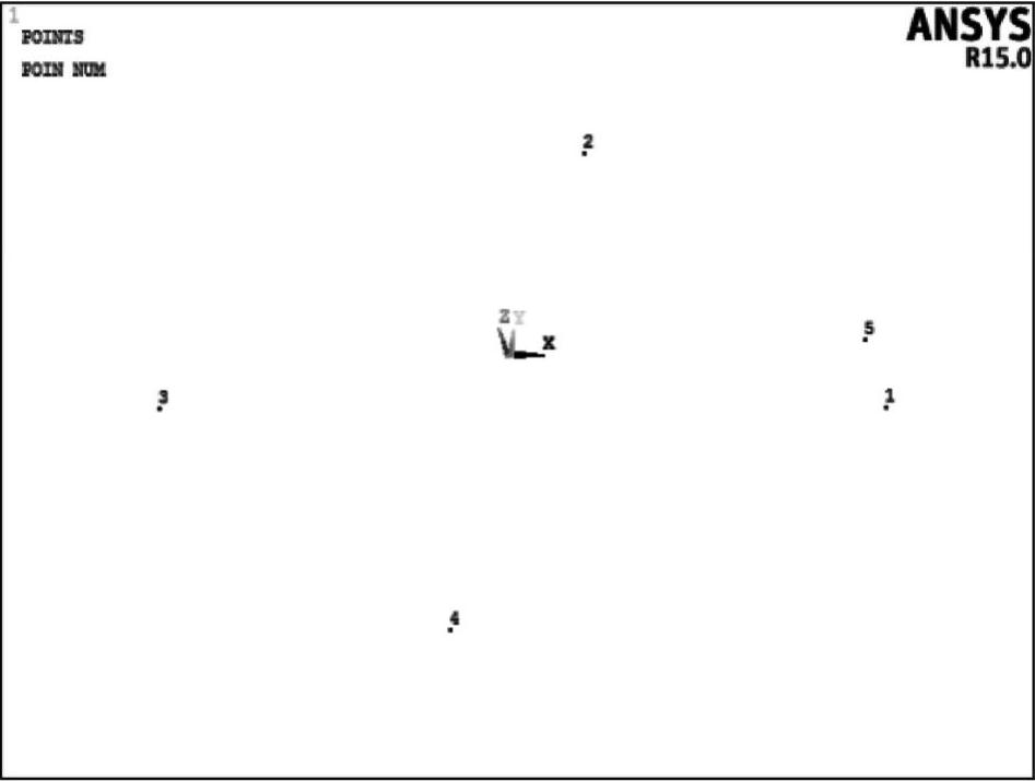
图8-3 定义关键点
5)完成点的定义后,将之连成线。在GUI界面中选择Main Menu>Preprocessor>Modeling>Create>Lines>Lines>In Active Coord命令,依次拾取工作区中的点1、2,单击Apply按钮,连接1、2号关键点。继续完成2、3号关键点,3、4号关键点,4、5号关键点的连接,结果如图8-4所示。
6)在GUI界面中选择Main Menu>Preprocessor>Modeling>Copy>Lines命令,单击Pick All按钮,弹出如图8-5所示的Copy Lines对话框。
设置复制份数为7,偏移量为DY=0.002。单击OK按钮完成复制,完成复制的线如图8-6所示。
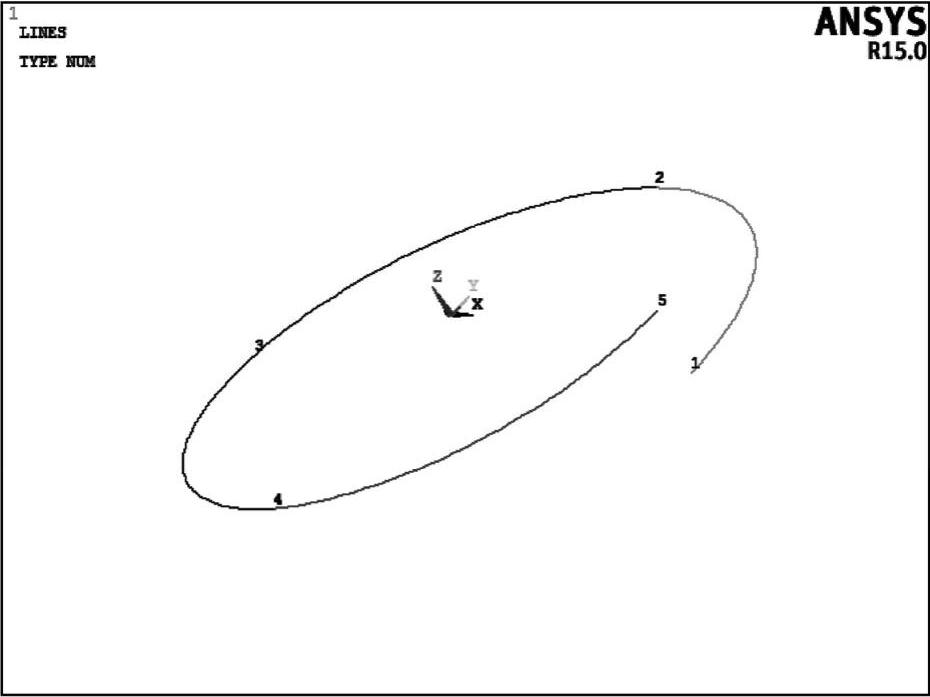
图8-4 连接直线
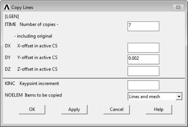
图8-5 Copy Lines对话框
7)在GUI界面中选择Main Menu>Preprocessor>Numbering Ctrls>Merge Items命令,弹出图8-7所示的Merge Coincident of Equivalently Defined Items对话框,设置合并项如图8-7所示,单击OK按钮完成编号压缩。
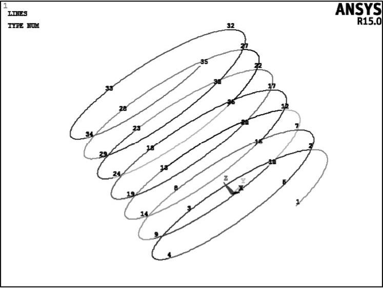
图8-6 完成线的复制
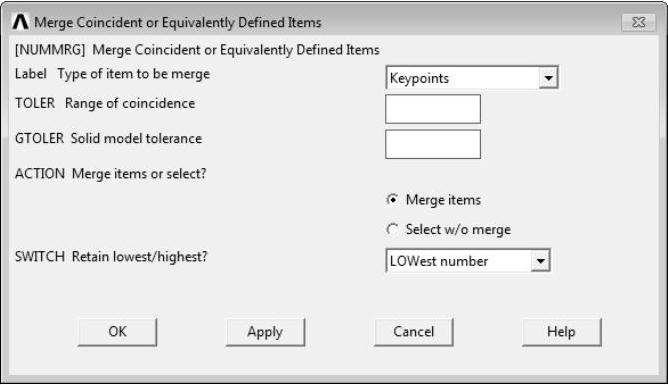
图8-7 Merge Coincident of Equivalently Defined Items对话框
8)在GUI界面中选择Main Menu>Preprocessor>Modeling>Operate>Booleans>Add>Lines命令,单击Pick All按钮,将所有线相加。
9)在GUI界面中选择Main Menu>Preprocessor>Modeling>Create>Keypoints>In Active CS命令,弹出Create Keypoints in Active Coordinate System对话框。
在Create Keypoints in Active Coordinate System对话框定义80~83号关键点,坐标位置列于表8-2中,完成定义关键点如图8-8所示。
表8-2 关键点列表

10)在GUI界面中选择Main Menu>Preprocessor>Modeling>Create>Lines>Lines>In Active Coord命令,依次拾取工作区中的点35、80,单击Apply按钮,继续拾取,依次将80与81、81与82、82与83按顺序连接,连接完成的线如图8-9所示。
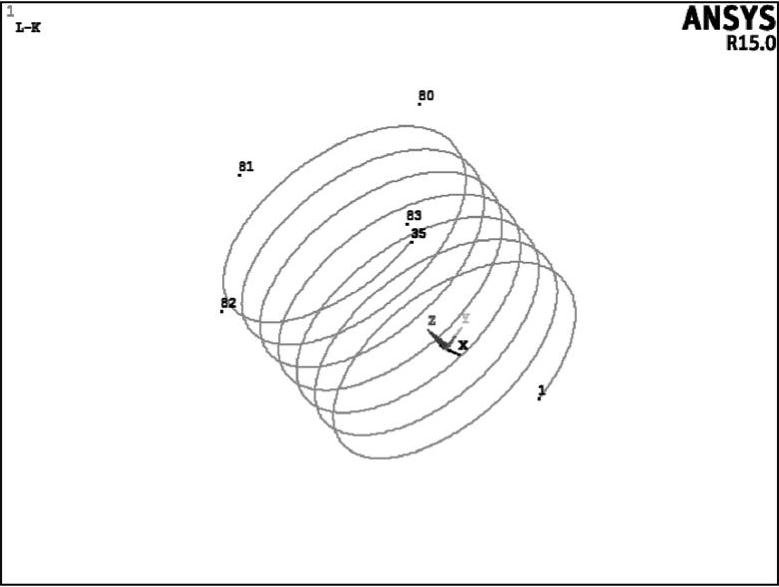
图8-8 定义关键点
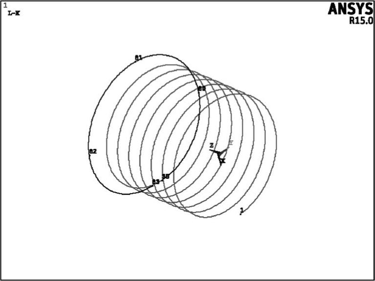
图8-9 连线
11)在GUI界面中选择Utility Menu>WorkPlane>Change Active CS to>Global Cartesian命令,将全局坐标系设置为笛卡儿坐标系。
12)在GUI界面中选择Main Menu>Preprocessor>Modeling>Create>Keypoints>In Active CS命令,弹出Create Keypoints in Active Coordinate System对话框。
在Create Keypoints in Active Coordinate System对话框定义90~92号关键点,坐标位置列于表8-3中,完成定义关键点如图8-10所示。
表8-3 关键点坐标

13)在GUI界面中选择Main Menu>Preprocessor>Modeling>Create>Lines>Lines>Straight Line命令,拾取点1、90,单击Apply按钮,再拾取点91、92,将上述点连接成直线。
在GUI界面中选择Main Menu>Preprocessor>Modeling>Create>Lines>Lines>At angle to line命令,拾取工作区中的7号线,单击OK按钮,拾取90号关键点,单击OK按钮,输入旋转角度为60。
复上述操作,旋转对象为7号线,旋转点为1号点,旋转角度为120。截面轮廓如图8-11所示。
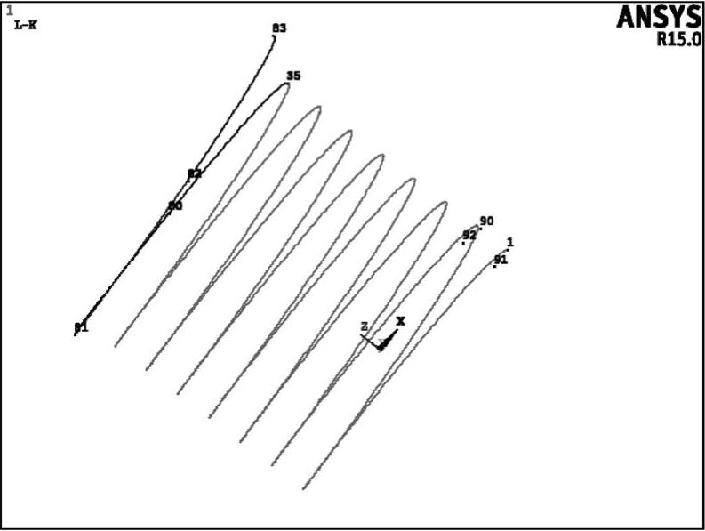
图8-10 螺纹截面关键点
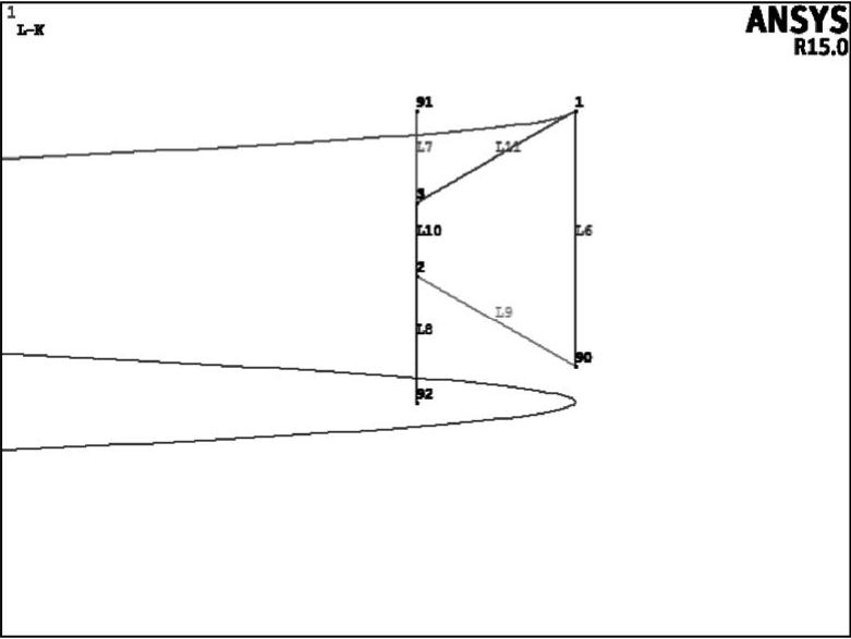
图8-11 螺纹截面轮廓
14)在GUI界面中选择Main Menu>Preprocessor>Modeling>Create>Areas>Arbitrary>By Lines命令,拾取工作区中的6、9、10、11号线,单击OK按钮,完成截面定义如图8-12所示。
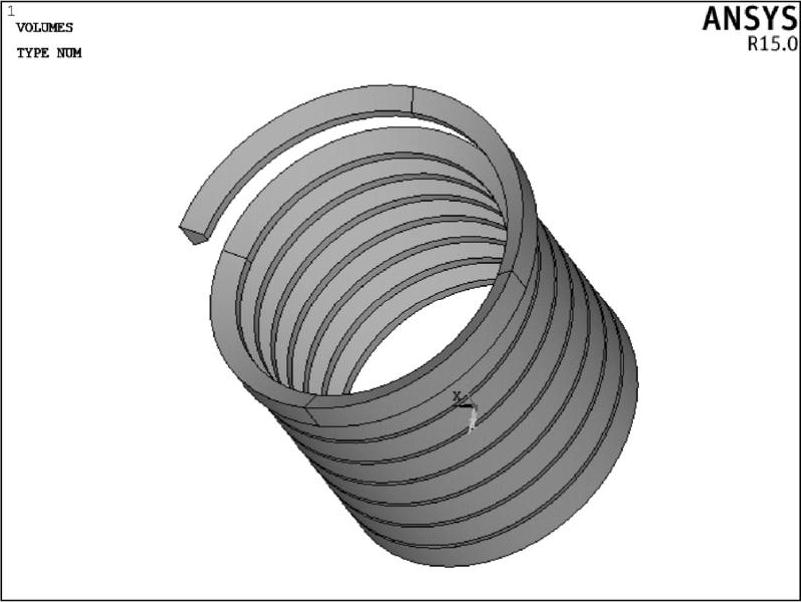
15)在GUI界面中选择Main Menu>Preprocessor>Modeling>Operate>Extrude>Areas>Along Lines命令,拾取螺纹截面,单击OK按钮,再拾取所有螺旋线,单击OK按钮,完成螺纹槽的定义如图8-13所示。
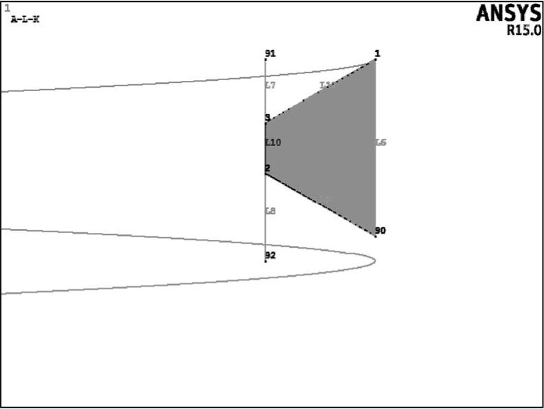
图8-12 螺纹截面
 (https://www.xing528.com)
图8-13 螺纹槽
16)在GUI界面中选择Main Menu>Preprocessor>Modeling>Create>Volumes>Cylinder>By Dimensions命令,弹出图8-14所示的Create Cylinder by Dimensions对话框,输入圆柱参数如图8-14所示。
单击OK按钮生成螺栓体如图8-15所示。
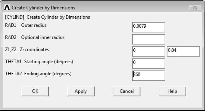
图8-14 Create Cylinder by Dimensions对话框
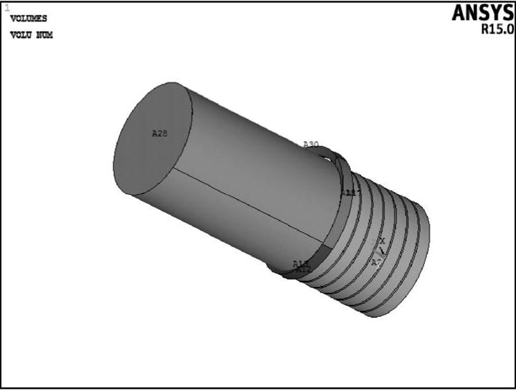
图8-15 生成螺栓体
17)在GUI界面中选择Utility Menu>Select>Entities命令,在Select Entities对话框中设置选择对象为Volumes,选择方式为Unselect,单击OK按钮,拾取上一步生成的螺栓体,单击OK按钮。
18)在GUI界面中选择Utility Menu>Select>Comp/Assembly>Create Component命令,弹出图8-16所示的Create Component对话框。
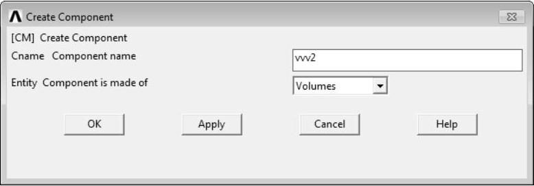
图8-16 Create Component对话框
输入组件名称,设置组合的对象为Volumes,单击OK按钮。
19)在GUI界面中选择Main Menu>Preprocessor>Modeling>Operate>Booleans>Subtract>Volumes命令,拾取螺栓体,单击OK按钮,然后在拾取框中输入vvv2,单击OK按钮,完成相减操作,如图8-17所示。
在GUI界面中选择Main Menu>Preprocessor>Modeling>Create>Keypoints>In Active CS命令,弹出Create Keypoints in Active Coordinate System对话框。
在Create Keypoints in Active Coordinate System对话框定义93~96号关键点,坐标位置列于表8-4关键点列表中,完成定义关键点如图8-18所示。
表8-4 关键点列表

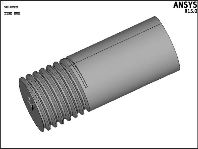
图8-17 生成螺纹
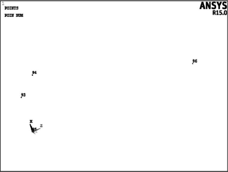
图8-18 93~96号关键点
20)在GUI界面中选择Main Menu>Preprocessor>Modeling>Create>Lines>Lines>Straight Line命令,拾取93、94号关键点,连接成为直线,如图8-19所示。
在GUI界面中选择Main Menu>Preprocessor>Modeling>Operate>Extrude>Lines>About Axis命令,拾取93、94号关键点连接线,单击OK按钮,单击95、96号关键点,单击OK按钮。生成的曲面如图8-20所示。
21)在GUI界面中选择Utility Menu>Select>Entities命令,在Select Entities对话框中设置选择对象为Areas,选择方式为From Full Set,单击OK按钮,拾取上一步生成的倒角面,单击OK按钮。此时工作区中的面如图8-21所示。
在GUI界面中选择Main Menu>Preprocessor>Modeling>Operate>Booleans>Divide>Volume by Area命令,输入体号7,单击OK按钮,然后单击Pick All按钮,完成倒角分割。
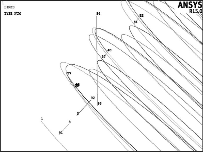
图8-19 连线
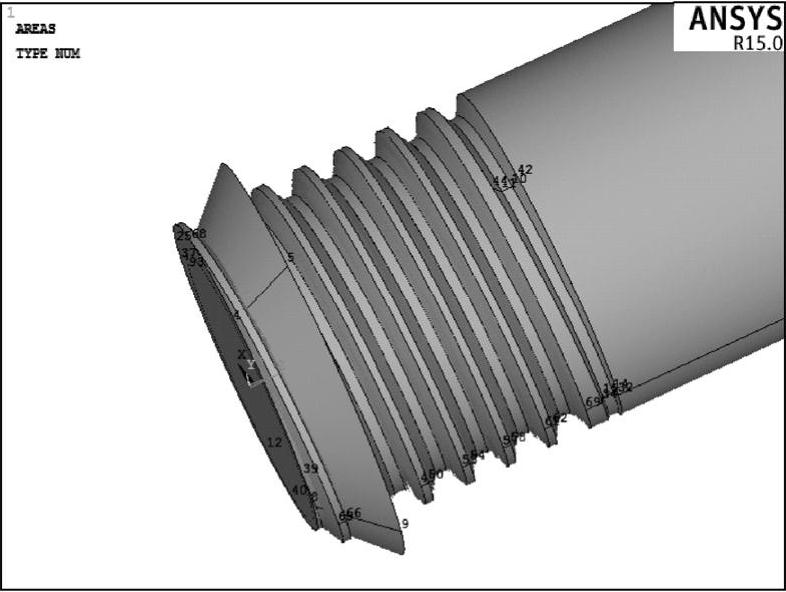
图8-20 旋转曲面
在GUI界面中选择Utility Menu>Select>Everything命令,然后在GUI界面中选择Main Menu>Preprocessor>Modeling>Delete>Volume and Below命令,拾取应删去的倒角部分,单击OK按钮,完成倒角如图8-22所示。
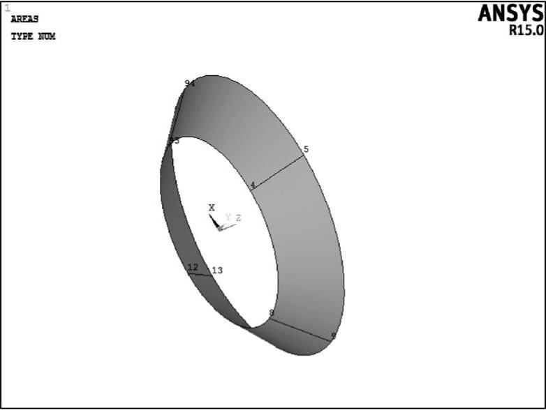
图8-21 选择中倒角面
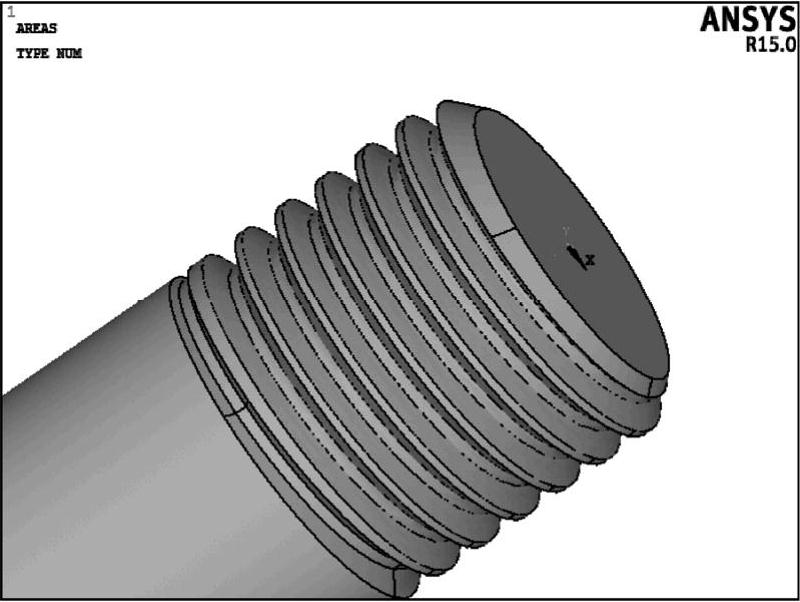
图8-22 倒角
22)在GUI界面中选择Main Menu>Preprocessor>Modeling>Create>Volumes>Prism>By Inscribed Rad命令,弹出图8-23所示的Prism by Inscribed Radius对话框,输入参数如图8-23所示。
单击OK按钮生成六角螺栓头如图8-24所示。
23)在GUI界面中选择Main Menu>Preprocessor>Modeling>Create>Volumes>Cone>By Dimensions命令,弹出图8-25所示的Create Cone by Dimesions对话框,输入参数如图8-25所示。
单击OK按钮,生成螺栓头的倒圆如图8-26所示。
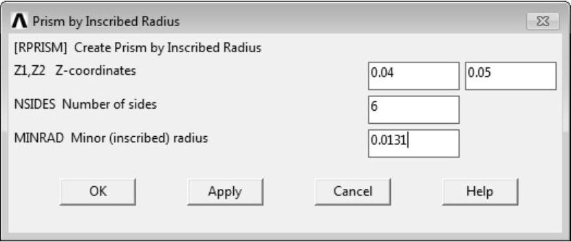
图8-23 Prism by Inscribed Radius对话框
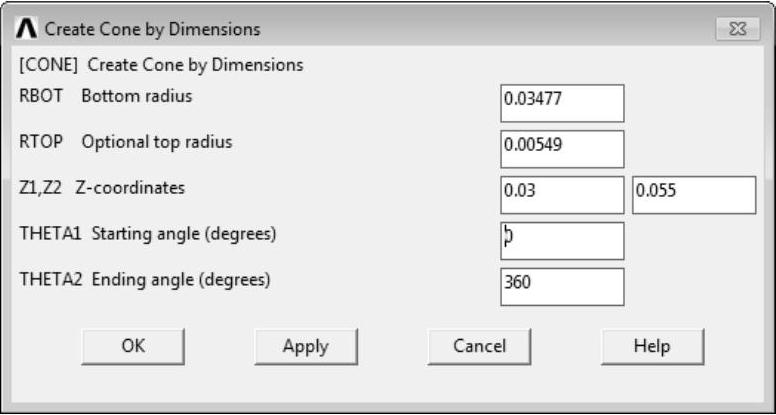
图8-25 Create Cone by Dimesions对话框
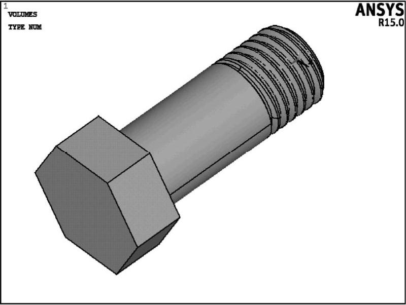
图8-24 生成螺栓头
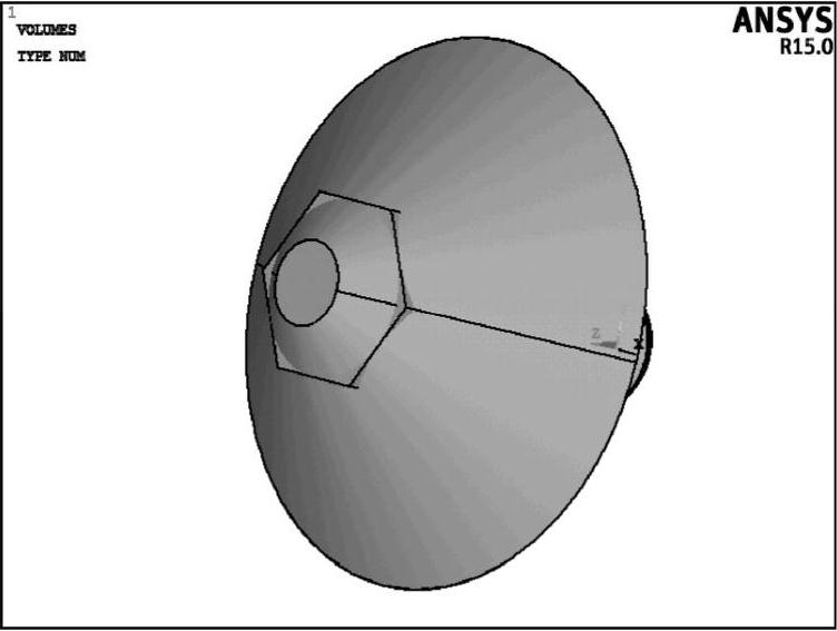
图8-26 倒圆面
24)在GUI界面中选择Main Menu>Preprocessor>Modeling>Operate>Booleans>Intersect>Common>Volumes命令,先拾取六角螺栓头,单击OK按钮,再拾取倒圆面,单击OK按钮,
完成螺栓头的倒圆角如图8-27所示。
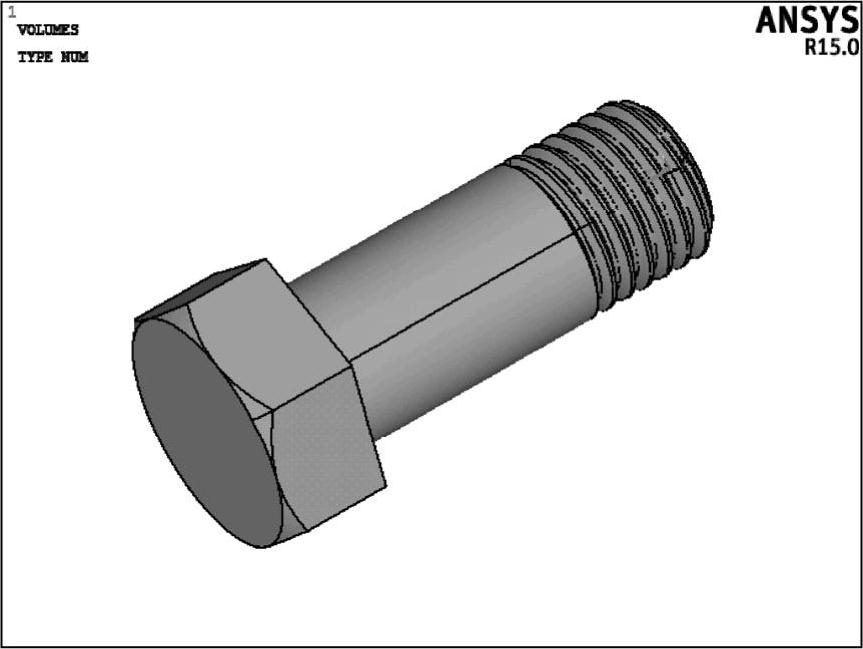
图8-27 倒圆角
至此完成螺栓模型的建立。
免责声明:以上内容源自网络,版权归原作者所有,如有侵犯您的原创版权请告知,我们将尽快删除相关内容。


