(1)单击Build > Hardpoind > New命令,弹出创建硬点对话框,如图7-3所示。在下列对话框中输入相应的数据:

图7-3 硬点创建对话框
· Hardpoint Name:arb_bushing;
· Type:left;
· Location(置文本框):0.0,-254.0,0.0。
(2)单击Apply按钮,完成._FSAE_arb_rigid.ground.hpl_arb_bushing硬点的创建;此时在屏幕上显示出左右对称的两个硬点;以此类推,重复上述步骤完成图7-4中硬点的创建。

图7-4 硬点数据
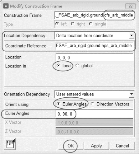
(3)单击Build > Construction Frame > New命令,创建结构框,如图7-5所示。在下列对话框中输入相应的数据:

图7-5 结构框
· Construction Frame(结构框名称):arb_middle;
· Location Dependency:Delta location from coor arb_middledinate;
· Coordinate Reference(参考坐标):._FSAE_arb_rigid.ground.hps_arb_middle;
· Location:0,0,0;
· Location in:local;
· Orientation Dependency:User entered values;
· Orient using:Euler Angles;
· Euler Angles:0,90,0。
(4)单击Apply按钮,完成._FSAE_arb_rigid.ground.cfs_arb_middle结构框的创建。同理,创建其他结构框。
· Construction Frame(结构框名称):arb_bend;
· Location Dependency:Delta location from coor arb_middledinate;
· Coordinate Reference(参考坐标):._FSAE_arb_rigid.ground.hpl_arb_bend;
· Location:0,0,0。
· Location in:local;
· Orientation Dependency:User entered values;
· Orient using:Euler Angles;
· Euler Angles:0,0,0。
(5)单击Apply按钮,完成._FSAE_arb_rigid.ground.cfl_arb_bend结构框的创建。
· Construction Frame(结构框名称):droplink_to_arb;
· Location Dependency:Delta location from coor arb_middledinate;
· Coordinate Reference(参考坐标):._FSAE_arb_rigid.ground.hpl_droplink_to_arb;
· Location:0,0,0;
· Location in:local;
· Orientation Dependency:User entered values;
· Orient using:Euler Angles;
· Euler Angles:0,0,0。
(6)单击OK按钮,完成._FSAE_arb_rigid.ground.cfl_droplink_to_arb结构框的创建。
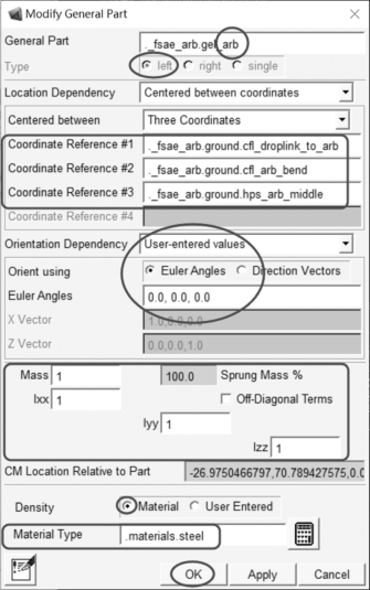
(7)单击Build > Part > General Part > New命令,弹出创建扭杆部件对话框,如图7-6所示。在下列对话框中输入相应的数据:
 (https://www.xing528.com)
图7-6 扭杆部件_arb
· General Part:arb;
· Location Dependency:Centered between coordinates;
· Centered between:Three Coordinates;
· Coordinate Reference #1(参考坐标):._FSAE_arb_rigid.ground.cfl_droplink_to_arb;
· Coordinate Reference #2(参考坐标):._FSAE_arb_rigid.ground.cfl_arb_bend;
· Coordinate Reference #3(参考坐标):._FSAE_arb_rigid.ground.cfs_arb_middle;
· Orientation Dependency:User entered values;
· Orient using:Euler Angles;
· Euler Angles:0,0,0;
· Mass:1;
· Ixx:1;
· Iyy:1;
· Izz:1;
· Density:Material;
· Material Type:.materials.steel。
(8)单击OK按钮,完成部件._FSAE_arb_rigid.gel_arb的创建。
(9)单击Build > Geometry > Link > New命令,弹出扭杆几何体对话框,如图7-7所示。在下列对话框中输入相应的数据:

图7-7 扭杆几何体arb_mainbar
· Link Name(连杆名称):arb_mainbar;
· General Part:._FSAE_arb_rigid.gel_arb;
· Coordinate Reference #1(参考坐标):._FSAE_arb_rigid.ground.cfs_arb_middle;
· Coordinate Reference #2(参考坐标):._FSAE_arb_rigid.ground.cfl_arb_bend;
· Radius(半径):8;
· Color(杆件几何体颜色):yellow;
· 选择Calculate Mass Properties of General Part复选框,当几何体建立好之后,会更新对应部件的质量和惯量参数;
· Density:Material;
· Material Type:steel。
(10)单击Apply按钮,完成arb_mainbar几何体的创建。同理,创建其他几何体。
· Link Name(连杆名称):arb_arm;
· General Part:._FSAE_arb_rigid.gel_arb;
· Coordinate Reference #1(参考坐标):._FSAE_arb_rigid.ground.cfl_arb_bend;
· Coordinate Reference #2(参考坐标):._FSAE_arb_rigid.ground.cfl_droplink_to_arb;
· Radius(半径):8;
· Color(杆件几何体颜色):yellow;
· 选择Calculate Mass Properties of General Part复选框,当几何体建立好之后,会更新对应部件的质量和惯量参数;
· Density:Material;
· Material Type:steel。
(11)单击OK按钮,完成arb_arm几何体的创建。
免责声明:以上内容源自网络,版权归原作者所有,如有侵犯您的原创版权请告知,我们将尽快删除相关内容。


