(1)单击File > New 命令,弹出创建模板对话框,如图2-2所示。在下列对话框中输入相应的数据:

图2-2 车身模板创建对话框
· Template Name:fsae_chassis;
· Major Role:body。
(2)单击OK按钮,完成车身模板的创建。
1.车身硬点参数
(1)单击Build > Hardpoind > New命令,弹出创建硬点对话框,如图2-3所示。在下列对话框中输入相应的数据:
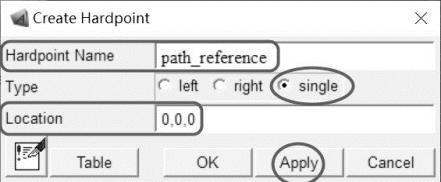
图2-3 硬点创建对话框
· Hardpoind Name:path_reference;
· Type:single;
· Location:0.0,0.0,0.0。
(2)单击Apply按钮,完成path_reference硬点的创建。创建另外一个硬点:
· Hardpoind Name:ground_height_reference;
· Type:single;
· Location:0.0,0.0,0.0。
(3)单击Apply按钮,完成ground_height_reference硬点的创建。
2.结构框参数
(1)单击Build > Construction Frame > New命令,创建定向结构框,如图2-4所示。在下列对话框中输入相应的数据:
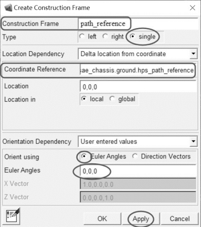
图2-4 结构框path_reference
· Construction Frame(结构框名称):path_reference;
· Type:single;
· Location Dependency:Delta location from coordinate;
· Coordinate Reference(参考坐标):._fsae_chassis.ground.hps_path_reference;
· Location:0,0,0;
· Location in:local;
· Orientation Dependency:User entered values;
· Orient using:Euler Angles;
· Euler Angles:0,0,0。
(2)单击Apply按钮,完成._fsae_chassis.ground.cfs_path_reference结构框的创建。继续创建其他结构框:
· Construction Frame(结构框名称):driver_reference;
· Type:single;
· Location Dependency:Delta location from coordinate;
· Coordinate Reference(参考坐标):._fsae_chassis.ground.hps_path_reference;
· Location:0,0,0;
· Location in:local;
· Orientation Dependency:User entered values;
· Orient using:Euler Angles;
· Euler Angles:180,0,0。
(3)单击Apply按钮,完成._fsae_chassis.ground.cfs_driver_reference结构框的创建。
· Construction Frame(结构框名称):aero_force_reference;
· Type:single;
· Location Dependency:Delta location from coordinate;
· Coordinate Reference(参考坐标):._fsae_chassis.ground.hps_ground_height_reference;
· Location:0,0,0;
· Location in:local;
· Orientation Dependency:User entered values;(https://www.xing528.com)
· Orient using:Euler Angles;
· Euler Angles:90,90,180。
(4)单击OK按钮,完成._fsae_chassis.ground.cfs_aero_force_reference结构框的创建。
3.车身部件与几何体
(1)单击Build > Part > General Part > New命令,创建部件,如图2-5所示。在下列对话框中输入相应的数据:
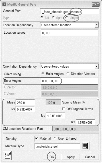
图2-5 车身部件对话框
· General Part:chassis;
· Location Dependency:User-entered location;
· Location values:0,0,0;
· Orientation Dependency:User-entered values;
· Orient using:Euler Angles;
· Euler Angles:0,0,0;
· Mass:260;
· Ixx:5.23e7;
· Iyy:1.31e8;
· Izz:1.57e8;
· Density:Material;
· Material Type:.materials.steel。
(2)单击OK按钮,完成车身部件._fsae_chassis.ges_chassis的创建。
(3)单击Build > Geometry > Ellipsoid > New命令,创建椭圆几何体,如图2-6所示。在下列对话框中输入相应的数据:
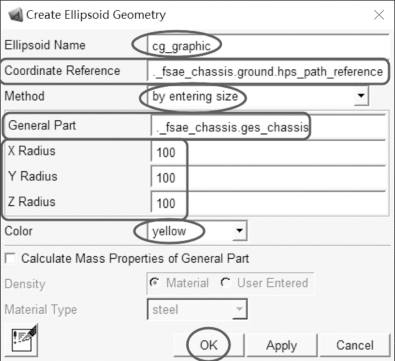
图2-6 椭圆几何体对话框
· Ellipsoid Name(椭圆体名称):cg_graphic;
· Coordinate Reference(参考坐标):._fsae_chassis.ground.hps_path_reference;
· Method:by entering size;
· General Part:._fsae_chassis.ges_chassis;
· X Radius:100;
· Y Radius:100;
· Z Radius:100;
· Color(杆件几何体颜色):yellow;
· Density:Material;
· Material Type:steel。
(4)其余保持默认设置,单击OK按钮,完成cg_graphic几何体的创建。
4.输出通信器
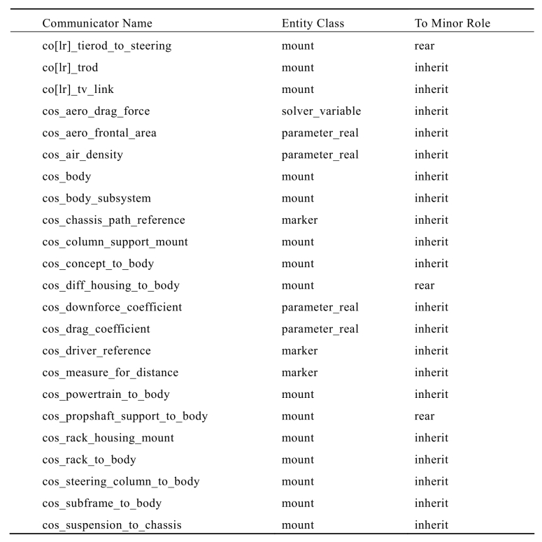
FSAE简化车身共包含26个输出通信器,具体见表2-1。
表2-1 车身通信器
(1)单击Build > Communicator > Output >New命令,弹出输出通信器对话框,如图2-7所示。在下列对话框中输入相应的数据:
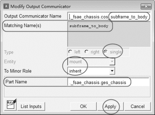
图2-7 输出通信器对话框
· Output Communicator Name(输出通信器名称):subframe_to_body;
· Matching Name(s):subframe_to_body;
· Type:single;
· Entity:mount;
· To Minor Role:inherit;
· Part Name:._fsae_chassis.ges_chassis。
(2)单击Apply按钮,完成通信器._fsae_chassis.cos_subframe_to_body的创建。
(3)重复上述步骤,按顺序完成表格中对应输出通信器的创建。
免责声明:以上内容源自网络,版权归原作者所有,如有侵犯您的原创版权请告知,我们将尽快删除相关内容。


