


Step1.复制并粘贴加工操作。右击特征树中的“Profile Contouring.3(Computed)”节点,在系统弹出的快捷菜单中选择 命令;再次右击特征树中的“Profile Contouring.3(Computed)”节点,在系统弹出的快捷菜单中选择
 命令,在“Profile Contouring.3(Computed)”节点下插入一个型腔铣削加工操作“Profile Contouring.4(Computed)”。
Step2.在特征树中双击节点“Profile Contouring.4(Computed)”,系统弹出“Profile Contouring.4”对话框(一)。
Step3.定义几何参数。
(1)进入几何参数选项卡。在“Profile Contouring.4”对话框中单击 选项卡。
选项卡。
(2)定义侧面轮廓。右击“Profile Contouring.4”对话框中的侧面轮廓感应区,在系统弹出的快捷菜单中选择 命令,再次单击侧面轮廓感应区,然后在图形区选择图19.66所示的轮廓线,在图形区空白处双击鼠标左键,系统返回到“Profile Contouring.3”对话框。
说明:如果是复制并粘贴的加工操作,这里只需要调节侧面轮廓,其余参数与上一个加工操作完全相同。
Step4.定义刀具等其他参数。系统自动继承了前面的设置,这里不用调整。(https://www.xing528.com)
Step5.刀路仿真。在“Profile Contouring.4”对话框(一)中单击“Tool Path Replay”按钮 ,系统弹出“Profile Contouring.4”对话框(二),且在图形区显示刀路轨迹(图19.67)。
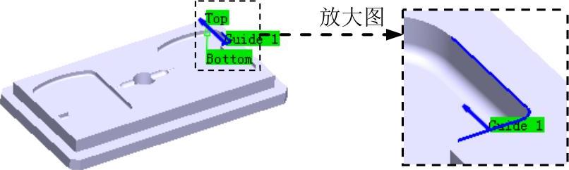
图19.66 定义侧面轮廓
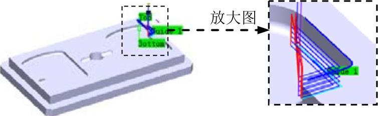
图19.67 显示刀路轨迹
Step6.在“Profile Contouring.4”对话框(二)中单击 按钮,然后单击“Profile Contouring.4对话框(一)中的
 按钮。
按钮。
免责声明:以上内容源自网络,版权归原作者所有,如有侵犯您的原创版权请告知,我们将尽快删除相关内容。