任务引言
随着网络多元化的发展,网络的优化成为一大课题。负载均衡是解决分布式系统流量控制、网络冗余等问题的关键,是网络优化的重要措施。
学习目标
了解多实例生成树协议的原理;
熟悉多实例生成树实现流量负载均衡的方法。
知识引入
负载均衡建立在现有网络结构之上,它提供了一种扩展网络设备和服务器的带宽、增加吞吐量、加强网络数据处理能力、提高网络的灵活性和可用性的方法。
多实例生成树是在局域网中实现负载均衡的重要手段。快速生成树协议的根本目的是将一个存在物理环路的交换网络变成一个没有环路的逻辑树型网络,这样势必导致某两台交换机之间的链路处于阻塞状态。这也必然会导致某台交换机负荷加重。而多实例生成树协议能用少量的资源在网络中形成多个生成树,并且在多条Trunk链路上实现VLAN级的负载均衡。
1.工作任务背景
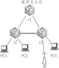
千山公司深圳总公司在配置生成树协议后,交换机s2和交换机s3之间的通信有了很大提高,但在使用一段时间后发现公司员工上外网的速度变得很慢。公司查看网络数据发现,不管是交换机s2还是交换机s3的数据都从s2-s1这条链路出去,而链路s3-s1则没有数据或有极少数据通过。因此要提高链路带宽利用率,就需要利用多实例生成树技术实现流量负载均衡,如图3-3-1所示。

图3-3-1 交换机多实例生成树协议配置
2.工作任务分析
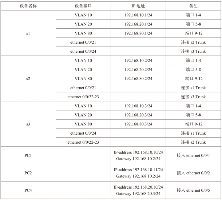
本任务采用三台交换机,在三台交换机之间形成一个环路,并分别在两台二层交换机连接PC1和PC2作为测试。当配置多实例生成树协议后,三台交换机之间的线路全部处于转发状态,并且转发数据能根据不同VLAN进行负载均衡。这就避免了当只在交换机上启用生成树协议时,三台交换机之间有一条链路是阻塞状态,给某台交换机增加负荷的问题。IP地址网络参数设置如表3-3-1所示。
表3-3-1 IP地址网络参数设置

【任务实现】
1.正确连接网线,恢复出厂设置之后做初始配置
交换机s1:
switch#config
s1(config)#hostname s1
s1(config)#vlan 10
s1(config-vlan10)#switchport interface ethernet 0/0/1-4
s1(config)#vlan 20
s1(config-vlan20)#switchport interface ethernet 0/0/5-8
s1(config)#interface ethernet 0/0/21
s1(config-if-ethernet0/0/21)#switchport mode trunk
s1(config)#interface ethernet 0/0/24
s1(config-if-ethernet0/0/24)#switchport mode trunk
s1(config)#intface vlan 10
s1(config-if-vlan10)#ip address 192.168.10.1 255.255.255.0
s1(config)#intface vlan 20
s1(config-if-vlan20)#ip address 192.168.20.1 255.255.255.0
s1(config)#intface vlan 80
s1(config-if-vlan80)#ip address 192.168.80.1 255.255.255.0
s1(config)#spanning-tree
交换机s2:
switch#config
switch (config)#hostname s2
s2(config)#vlan 10
s2(config-vlan10)#switchport interface ethernet 0/0/1-4
s2(config-vlan10)#exit
s2(config)#vlan 20
s2(config-vlan20)#switchport interface ethernet 0/0/5-8
s2(config-vlan20)#exit
s2(config)#vlan 80
s2(config-vlan80)#switchport interface ethernet 0/0/9-12
s2(config-vlan80)#exit
s2(config)#interface ethernet 0/0/21
s2(Config-If-Ethernet0/0/21)#switchport mode trunk
s2(config)#port-group 1
s2(config)#interface ethernet 0/0/22-23
s2(Config-If-Port-Range)#port-group 1 mo on
s2(Config-If-Port-Range)#exit
s2(config)#interface port-channel 1
s2(Config-If-Port-Channel1)#switchport mode trunk
s2(Config-If-Port-Channel1)#exits
s2(config)#spanning-tree
s2(config)#spanning-tree mst configuration
s2(Config-Mstp-Region)#instance 1 vlan 10
s2(Config-Mstp-Region)#instance 2 vlan 20
s2(Config-Mstp-Region)#exit
s2(config)#spanning-tree mst 1 priority 0
s2(config)#spanning-tree mst 2 priority 4096
交换机s3:
switch(Config)#hostname s3
s3(Config)#l3-forward enable
s3(Config)#vlan 10
s3(Config-Vlan10)#switchport interface ethernet 0/0/1-4
s3(Config)#vlan 20
s3(Config-Vlan20)#switchport interface ethernet 0/0/5-8
s3(Config)#vlan 80
s3(Config-Vlan80)#switchport interface ethernet 0/0/9-12
s3(config)#int vlan 10
s3(Config-if-Vlan10)#ip address 192.168.10.3 255.255.255.0
s3(Config-if-Vlan10)#no shutdown
s3(Config-if-Vlan10)#exit
s3(config)#int vlan 20
s3(Config-if-Vlan20)#ip address 192.168.20.3 255.255.255.0
s3(Config-if-Vlan20)#no shutdown
s3(Config-if-Vlan20)#exit
s3(config)#int vlan 80
s3(Config-if-Vlan80)#ip address 192.168.80.3 255.255.255.0
s3(Config-if-Vlan80)#no shutdown
s3(Config-if-Vlan80)#exit
s3(config)#interface ethernet 0/0/24
s3(Config-If-Ethernet0/0/24)#switchport mode trunk
s3(Config-If-Ethernet0/0/24)#exit
s3(config)#port-group 1
s3(config)#interface ethernet 0/0/22-23
s3(Config-If-Port-Range)#port-group 1 mode on
s3(Config-If-Port-Range)#exit
s3(config)#interface port-channel 1
s3(Config-If-Port-Channel1)#switchport mode trunk
s3(Config-If-Port-Channel1)#exit
s3(config)#spanning-tree
s3(config)#spanning-tree mst configuration
s3(Config-Mstp-Region)#instance 1 vlan 10
s3(Config-Mstp-Region)#instance 2 vlan 20
s3(Config-Mstp-Region)#exit
s3(config)#spanning-tree mst 1 priority 0
s3(config)#spanning-tree mst 2 priority 4096
2.查看配置
交换机s2:
ss2(config)#show spanning-tree
-- MSTP Bridge Config Info --
Standard : IEEE 802.1s(https://www.xing528.com)
Bridge MAC : 00:03:0f:10:47:05
Bridge Times : Max Age 20, Hello Time 2, Forward Delay 15
Force Version: 3
########################### Instance 0 ###########################
Self Bridge Id : 32768 - 00:03:0f:10:47:05
Root Id : this switch
Ext.RootPathCost : 0
Region Root Id : this switch
Int.RootPathCost : 0
Root Port ID : 0
Current port list in Instance 0:
Ethernet0/0/1 Ethernet0/0/21 Port-Channel1 (Total 3)
PortName ID ExtRPC IntRPC State Role DsgBridge DsgPort
-------------- ------- --------- --------- --- ---- ------------------ ------
Ethernet0/0/1 128.001 0 0 FWD DSGN 32768.00030f104705 128.001
Ethernet0/0/21 128.021 0 0 FWD DSGN 32768.00030f104705 128.021
Port-Channel1 128.385 0 0 FWD DSGN 32768.00030f104705 128.385
########################### Instance 1 ###########################
Self Bridge Id : 0.00:03:0f:10:47:05
Region Root Id : this switch
Int.RootPathCost : 0
Root Port ID : 0
Current port list in Instance 1:
Ethernet0/0/1 Port-Channel1 (Total 2)
PortName ID IntRPC State Role DsgBridge DsgPort
-------------- ------- --------- --- ---- ------------------ -------
Ethernet0/0/1 128.001 0 FWD DSGN 0.00030f104705 128.001
Port-Channel1 128.385 0 FWD DSGN 0.00030f104705 128.385
########################### Instance 2 ###########################
Self Bridge Id : 4096.00:03:0f:10:47:05
Region Root Id : this switch
Int.RootPathCost : 0
Root Port ID : 0
Current port list in Instance 2:
Port-Channel1 (Total 1)
PortName ID IntRPC State Role DsgBridge DsgPort
-------------- ------- --------- --- ---- ------------------ -------
Port-Channel1 128.385 0 FWD DSGN 4096.00030f104705 128.385
交换机s3:
s3(config)#show spanning-tree
-- MSTP Bridge Config Info --
Standard : IEEE 802.1s
Bridge MAC : 00:03:0f:26:68:43
Bridge Times : Max Age 20, Hello Time 2, Forward Delay 15
Force Version: 3
########################### Instance 0 ###########################
Self Bridge Id : 32768 - 00:03:0f:26:68:43
Root Id : 32768.00:03:0f:10:47:05
Ext.RootPathCost : 100000
Region Root Id : this switch
Int.RootPathCost : 0
Root Port ID : 128.385
Current port list in Instance 0:
Ethernet0/0/5 Ethernet0/0/24 Port-Channel1 (Total 3)
PortName ID ExtRPC IntRPC State Role DsgBridge DsgPort
-------------- ------- --------- --------- --- ---- ------------------ ------
Ethernet0/0/5 128.005 100000 0 FWD DSGN 32768.00030f266843 128.005
Ethernet0/0/24 128.024 100000 0 FWD DSGN 32768.00030f266843 128.024
Port-Channel1 128.385 0 0 FWD ROOT 32768.00030f104705 128.385
########################### Instance 1 ###########################
Self Bridge Id : 0.00:03:0f:26:68:43
Region Root Id : this switch
Int.RootPathCost : 0
Root Port ID : 0
Current port list in Instance 1:
Ethernet0/0/24 Port-Channel1 (Total 2)
PortName ID IntRPC State Role DsgBridge DsgPort
-------------- ------- --------- --- ---- ------------------ -------
Ethernet0/0/24 128.024 0 FWD DSGN 0.00030f266843 128.024
Port-Channel1 128.385 0 FWD MSTR 0.00030f266843 128.385
########################### Instance 2 ###########################
Self Bridge Id : 4096.00:03:0f:26:68:43
Region Root Id : this switch
Int.RootPathCost : 0
Root Port ID : 0
Current port list in Instance 2:
Ethernet0/0/5 Ethernet0/0/24 Port-Channel1 (Total 3)
PortName ID IntRPC State Role DsgBridge DsgPort
-------------- ------- --------- --- ---- ------------------ -------
Ethernet0/0/5 128.005 0 FWD DSGN 4096.00030f266843 128.005
Ethernet0/0/24 128.024 0 FWD DSGN 4096.00030f266843 128.024
Port-Channel1 128.385 0 FWD MSTR 4096.00030f266843 128.385
3.验证配置
利用ping –t 命令让PC1 ping PC2并观察现象。
拔掉交换机s2端口21的网线,观察现象,出现了短暂中断,如图3-3-2所示。

图3-3-2 拔掉网线后的现象
再插上交换机s2端口4的网线,观察现象,同样出现了短暂中断,如图3-3-3所示。

图3-3-3 接入网线后的现象
【问题探究】
(1)多实例生成树是如何判断数据并决定其流向的?
(2)多实例生成树和快速生成树有什么区别?快速生成树能否实现流量负载均衡?
【知识拓展】
1.STP生成树协议
目的:为了防止冗余产生的环路。
原理:所有VLAN都加入一棵树里面,将备份链路的端口设为BLOCK,直到主链路出问题之后,BLOCK的链路才成为UP。端口的状态转换:
BLOCK>LISTEN>LERARN>FORWARD>DISABLE总共经历50s时间
缺点:收敛速度慢,效率低。
解决收敛速度慢的补丁:POSTFACT/UPLINKFAST(检查直连链路)/BACKBONEFAST(检查非直连链路)。
2.MSTP多生成树协议
目的:解决STP与RSTP中的效率低、占用资源的问题。
原理:部分VLAN为一棵树。
如果想在交换机上运行MSTP,首先必须在全局打开MSTP开关。在没有打开全局MSTP开关之前,打开端口的MSTP开关是不允许的。MSTP定时器参数之间是有相关性的,错误配置可能导致交换机不能正常工作。用户在修改MSTP参数时,应该清楚所产生的各个拓扑。除了全局的基于网桥的参数配置外,其他的是基于各个实例的配置,在配置时一定要注意参数对应的实例是否正确。DCS-3926S交换机的端口MSTP功能与端口MAC绑定、802.1x和设置端口为路由端口功能互斥。当端口已经配置MAC绑定、802.1x或设置端口为路由端口时,无法在该端口启用MSTP功能。
【任务拓展】
根据所学多实例生成树知识,完成图3-3-4所示网络的流量负载均衡设计与实现。

图3-3-4 交换机生成树协议配置
免责声明:以上内容源自网络,版权归原作者所有,如有侵犯您的原创版权请告知,我们将尽快删除相关内容。


