1)选择[File]>[Read]>[Profile...]菜单命令,选择“berl.prof”,导入数据曲线,如图5-25所示。
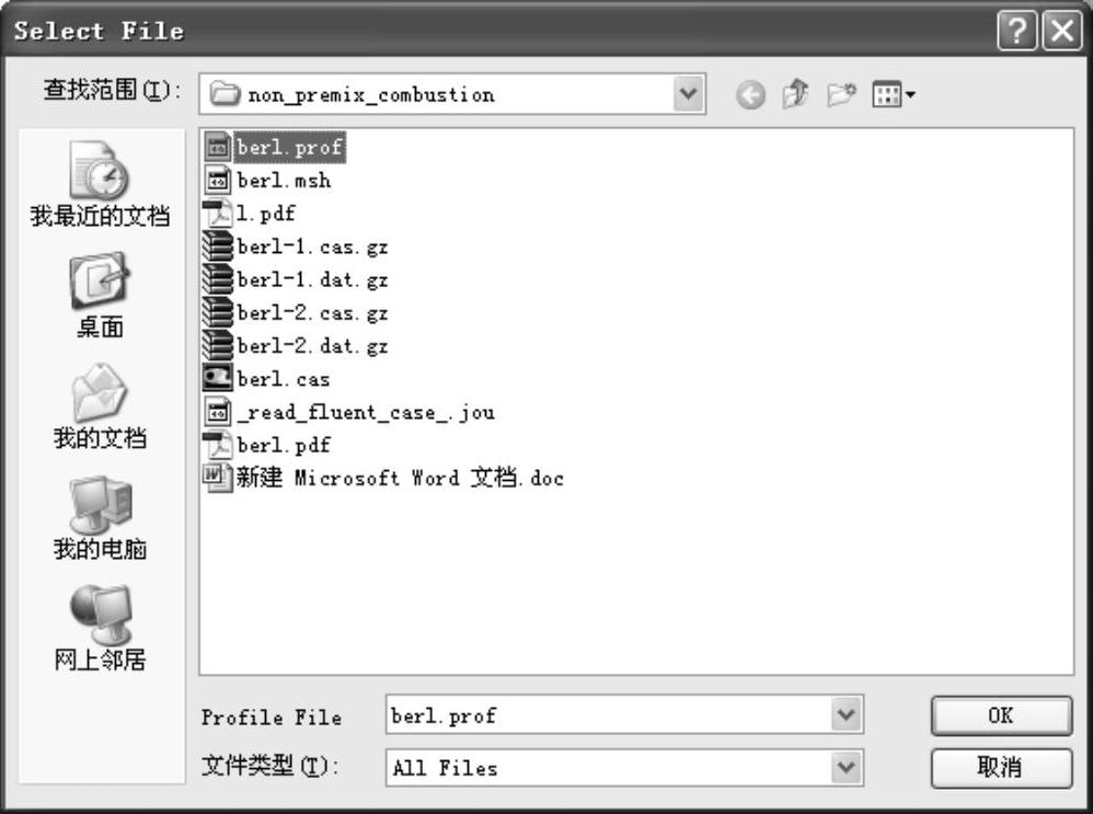
图5-25 导入数据曲线
2)保持树形菜单[Problem Setup]>[Boundary Conditions]>[poutlet-3]项为“pressure-outlet”条件。选择[Problem Setup]>[Boundary Conditions]>[poutlet-3]>[Edit...]项,打开“Pressure Outlet”对话框,如图5-26所示。
3)设置出口回流条件。将“Specification Method”项设置为“Intensity and Hydraulic Diameter”方式,同时将“Backflow Turbulent Intensity(%)”项设置为5,将“Backflow Hydraulic Diameter(mm)”项设置为600,如图5-27所示。
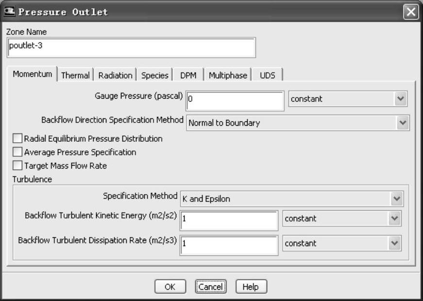
图5-26 “Pressure Outlet”对话框
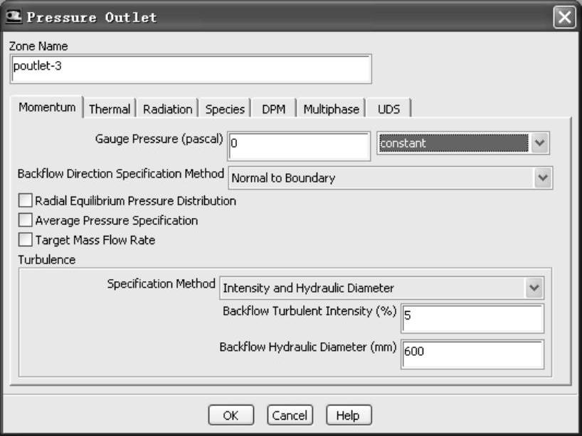
图5-27 设置出口回流条件
4)设置出口温度条件。切换到“Thermal”tab页,将“Backflow Total Temperature(K)”项设置为1310,如图5-28所示。单击“OK”按钮确认操作。
5)保持树形菜单中的[Problem Setup]>[Boundary Conditions]>[air-inlet-4]项为“velocity-inlet”条件。选择[Problem Setup]>[Boundary Conditions]>[air-inlet-4]>[Edit...]项,打开“VelocityInlet”对话框,如图5-29所示。
6)将“Velocity Specification Method”项设置为“Components”,将“Axial-Velocity”项设置为“vel-profu”,将“Radial-Velocity”项设置为“vel-profw”。设置入口湍流条件,将“Specification Method”项设置为“Intensity and Hydraulic Diameter”,同时将“Turbulent Intensity(%)”项设置为“17”,将“Hydraulic Diameter(mm)”项设置为“29”,如图5-30所示。
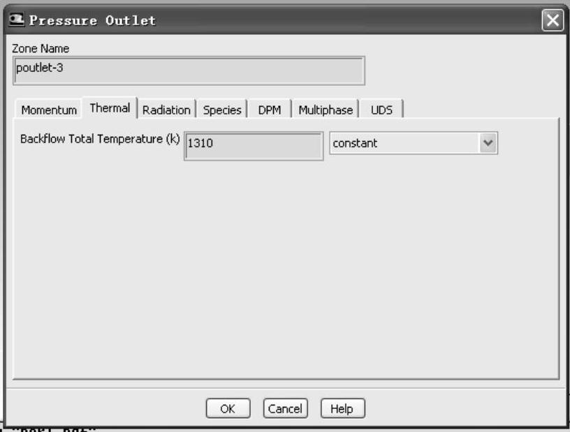
图5-28 设置出口温度条件
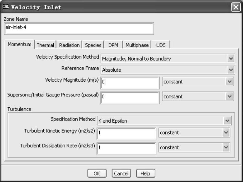
图5-29 设置air-inlet-4入口条件
7)设置入口温度条件。切换到“Thermal”tab页,将“Temperature(K)”项设置为322,如图5-31所示。单击“OK”按钮确认操作。
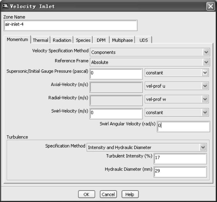
图5-30 设置air-inlet-4入口湍流条件
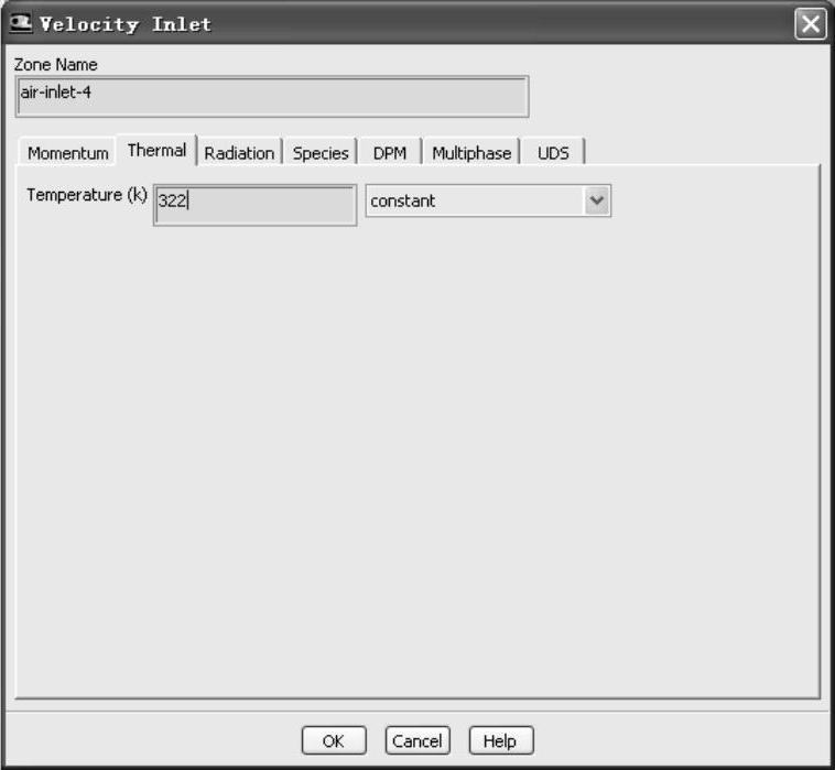
图5-31 设置air-inlet-4入口温度条件
8)保持树形菜单中的[Problem Setup]>[Boundary Conditions]>[fuel-inlet-5]项为“velocity-inlet”条件。选择[Problem Setup]>[Boundary Conditions]>[fuel-inlet-5]>[Edit...]项,打开“Velocity Inlet”对话框。
9)将“Velocity Specification Method”项设置为“Components”,将“Radial-Velocity(m/s)”项设置为“157.25”,将“Specification Method”项设置为“Intensityand Hydraulic Diameter”,同时将“Turbulent Intensity(%)”项设置为“5”,将“Hydraulic Diameter(mm)”项设置为“1.8”,如图5-32所示。
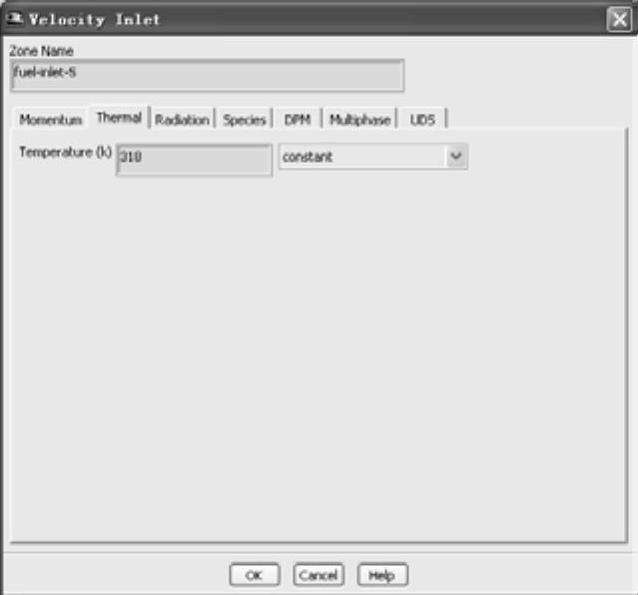
10)切换到“Thermal”tab页,将“Temperature(K)”项设置为318,如图5-33所示。
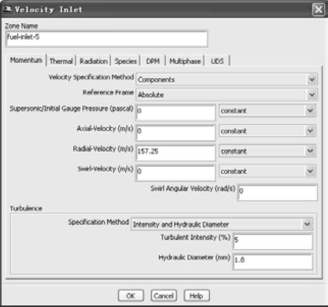
图5-32 设置fuel-inlet-5入口湍流条件
 (https://www.xing528.com)
图5-33 设置fuel-inlet-5入口温度条件
11)切换到“Species”tab页,将“Mean Mixture Fraction”项设置为1,如图5-34所示。单击“OK”按钮确认操作。
12)保持树形菜单中的[Problem Setup]>[Boundary Conditions]>[wall-6]项为“wall”条件。选择[Problem Setup]>[Boundary Conditions]>[wall-6]>[Edit...]项,打开“Wall”对话框,如图5-35所示。
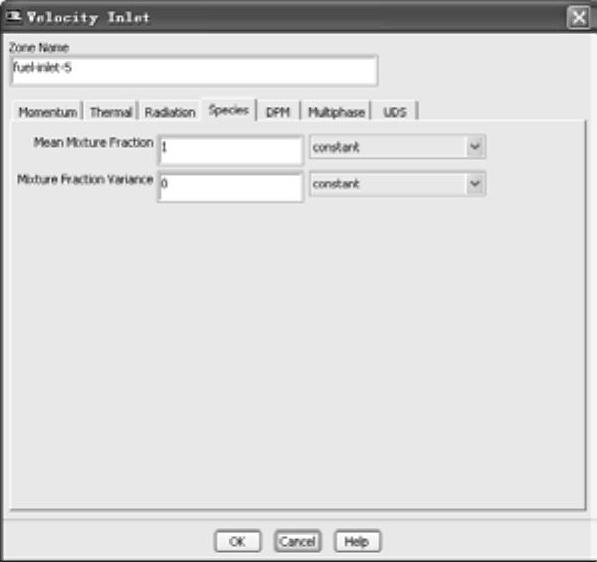
图5-34 设置“MeanMixtureFraction”条件
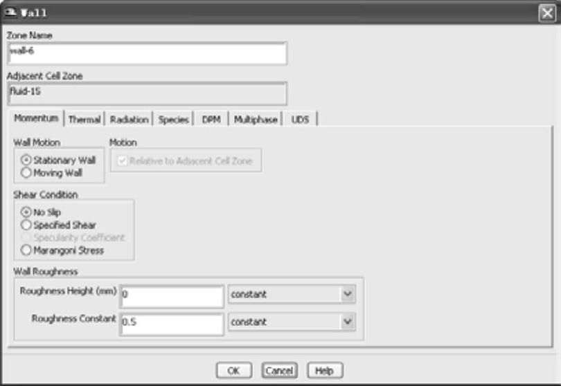
图5-35 设置wall-6壁面条件
13)切换到“Thermal”tab页,将“Thermal Conditions”项设置为“Temperature”,将“Temperature(K)”项设置为“1375”,将“Internal Emissivity”项设置为“0.55”,如图5-36所示。单击“OK”按钮确认操作。
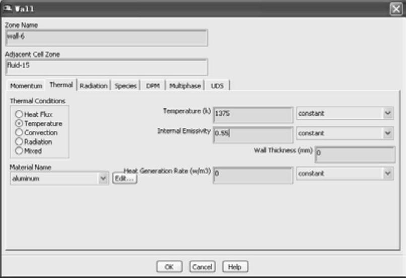
图5-36 设置wall-6壁面温度和发射率
14)重复以上操作,设置其余Wall边界,见表5-2。
表5-2 设置其余Wall边界

15)选择[Results]>[Plots]>[Profile Data]>[SetUp...]项,打开“Plot Profile Data”对话框,如图5-37所示。在“Profile”栏中选择“temp-prof”项(对应边界为wall-9),同时分别保持“Y Axis Function”项为“t”,保持“X Axis Function”项为“x”。
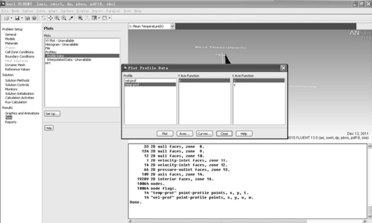
图5-37 选择“temp-prof”项
16)单击“Plot”按钮,绘制曲线,如图5-38所示。
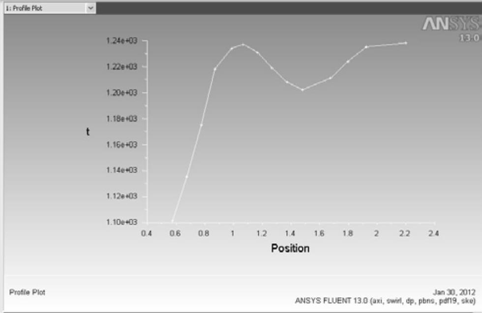
图5-38 绘制曲线
17)在“Plot Profile Data”对话框的“Profile”栏中选择“vel-prof”项(对应边界为air-inlet-4),同时分别保持“Y Axis Function”项为“u”,选择“X Axis Function”项为“y”。单击“Plot”按钮,视图区出现相应的曲线,如图5-39所示。
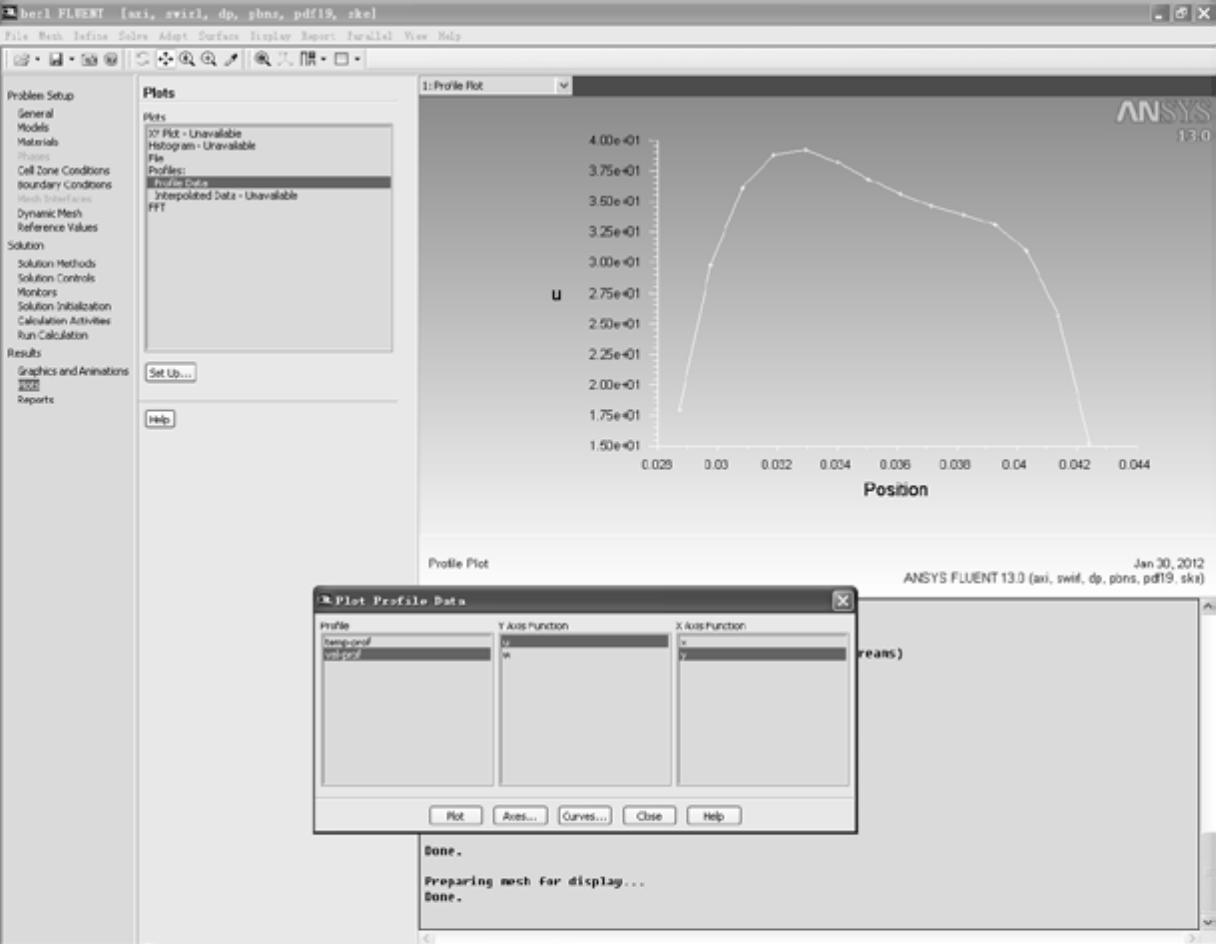
图5-39 选择“vel-prof”项
18)将图5-39中的“Y Axis Function”项设置为“w”,将“X Axis Function”项设置为“y”。单击“Plot”按钮,绘制曲线,如图5-40所示。
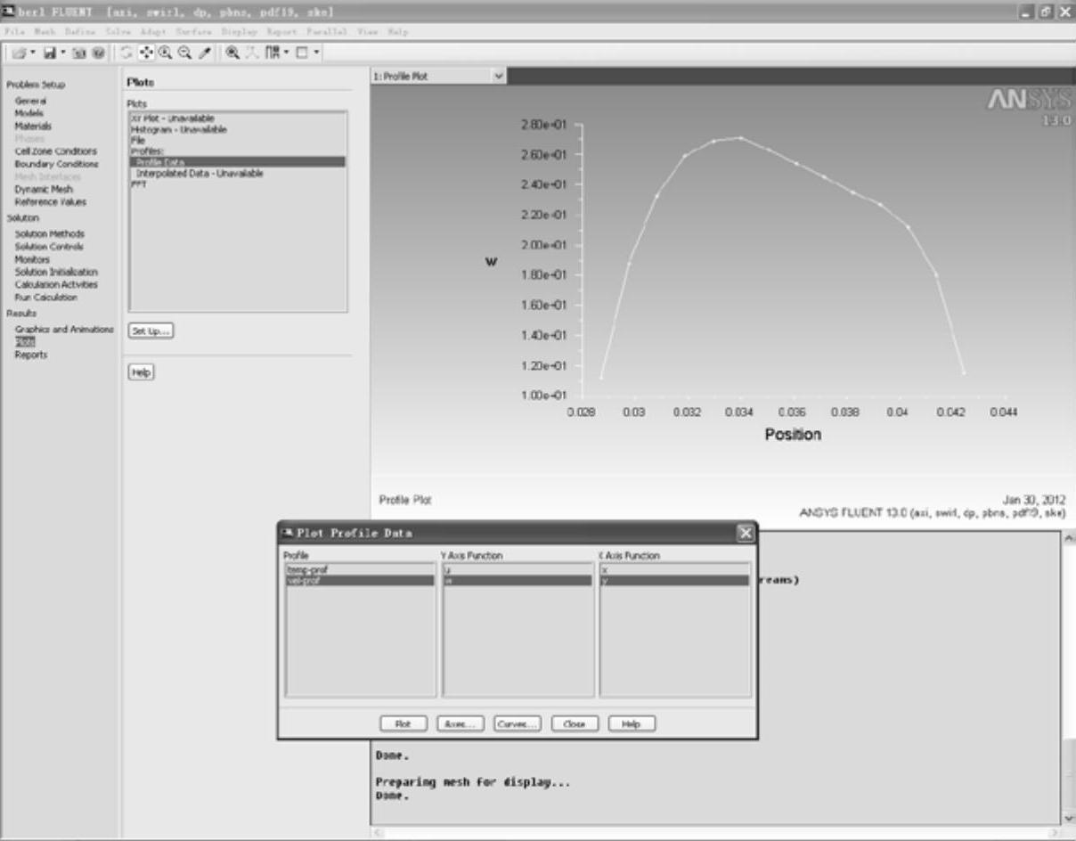
图5-40 绘制曲线
免责声明:以上内容源自网络,版权归原作者所有,如有侵犯您的原创版权请告知,我们将尽快删除相关内容。


